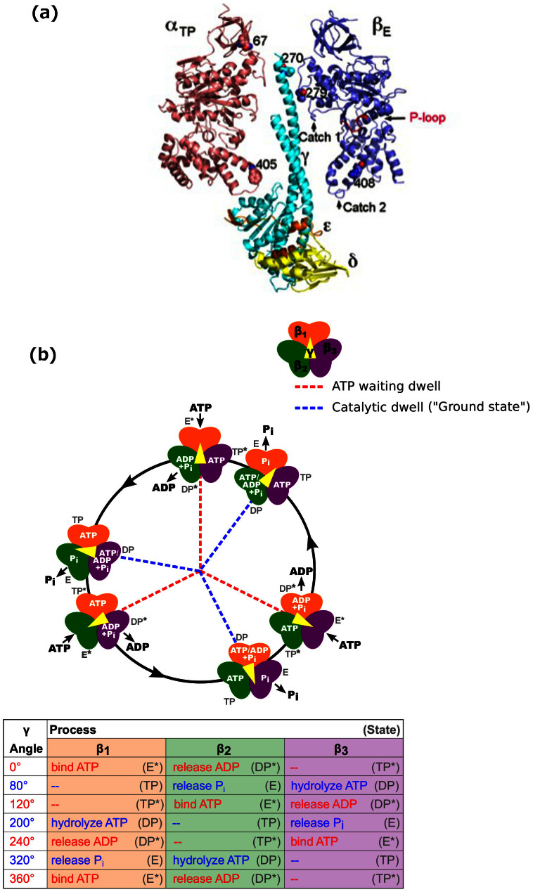
Figure 1. X-ray crystal structure and proposed mechanochemical cycle.
(A) Locations of the mgi residues in the X-ray crystal structure of yeast F1 (pdb: 2HLD, Complex I, Ref. 22). The αTP, βE, γ, δ, and ε subunits are shown along with the residues that were mutated for this study. Also shown are the Catch 1 and 2 regions which interact with the γ subunit and help define the structure of the catalytic sites. The P-loop, which forms part of the Pi and ATP binding site, is coloured in red and labelled. (B) A proposed mechanochemical coupling scheme of thermophilic F1. The catalytic sites of the three β subunits are shown in orange (β1), green (β2), and purple (β3). We define the 0° binding dwell to correspond to ATP binding at a particular site labelled β1 and ADP release at β241,54. The subunit shown in orange binds ATP at the 0° mark, and each subunit follows the processes and states listed in the table at the angles shown. The angular position of the γ subunit is represented by the central yellow arrow. Once a catalytic site binds an ATP molecule, it remains bound for 200° rotation of the γ subunit, whereupon it is hydrolysed. ADP is released at 240° and Pi at 320° from the binding site. Each β subunit completes one hydrolysis of an ATP molecule per 360° rotation of the γ subunit, and the three β subunits are staggered in their catalytic state by 120°. This means that at each ATP waiting dwell, ADP will release from one subunit and ATP will bind to the previous subunit. At each catalytic dwell, the ATP bound to one subunit will hydrolyze and the Pi from the previous subunit will be released. Refer to Refs. 2,3,4,5 for detailed reviews of the mechanochemical cycle of F1. Fig. redrawn from Ref. 2 with modifications.

