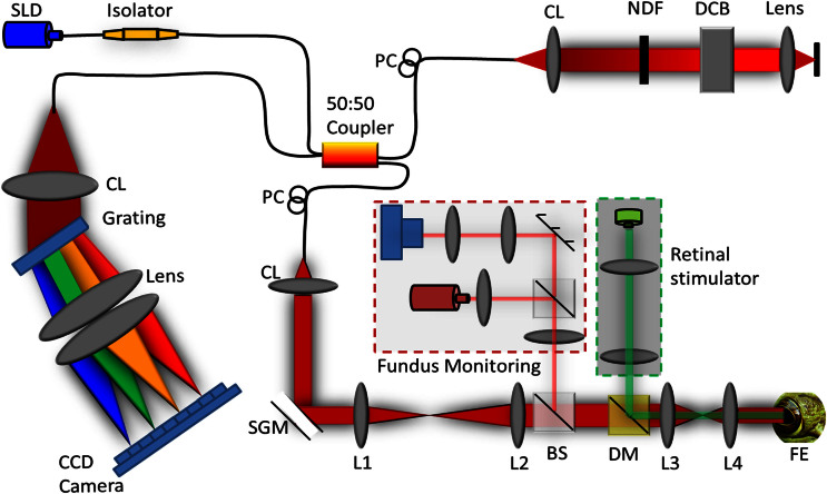
Figure 8. Schematic diagram of the experimental setup.
Schematic of the SD-OCT system configured with the retinal stimulator (indicated within green dashed line) and fundus camera (indicated within red dashed line) for in vivo functional IOS imaging of the retina. SLD: superluminescent diode, PC: polarization controller, CL: collimation lens, NDF: neutral density filter, DCB: dispersion compensating block, SGM: scanning galvanometer mirror, BS: beam splitter, DM: dichroic mirror, FE: frog eye, CCD: charge-coupled device, L1–L4: lens. Focal lengths of lenses L1, L2, L3 and L4 were 75 mm, 100 mm, 35 mm, and 25 mm, respectively.

