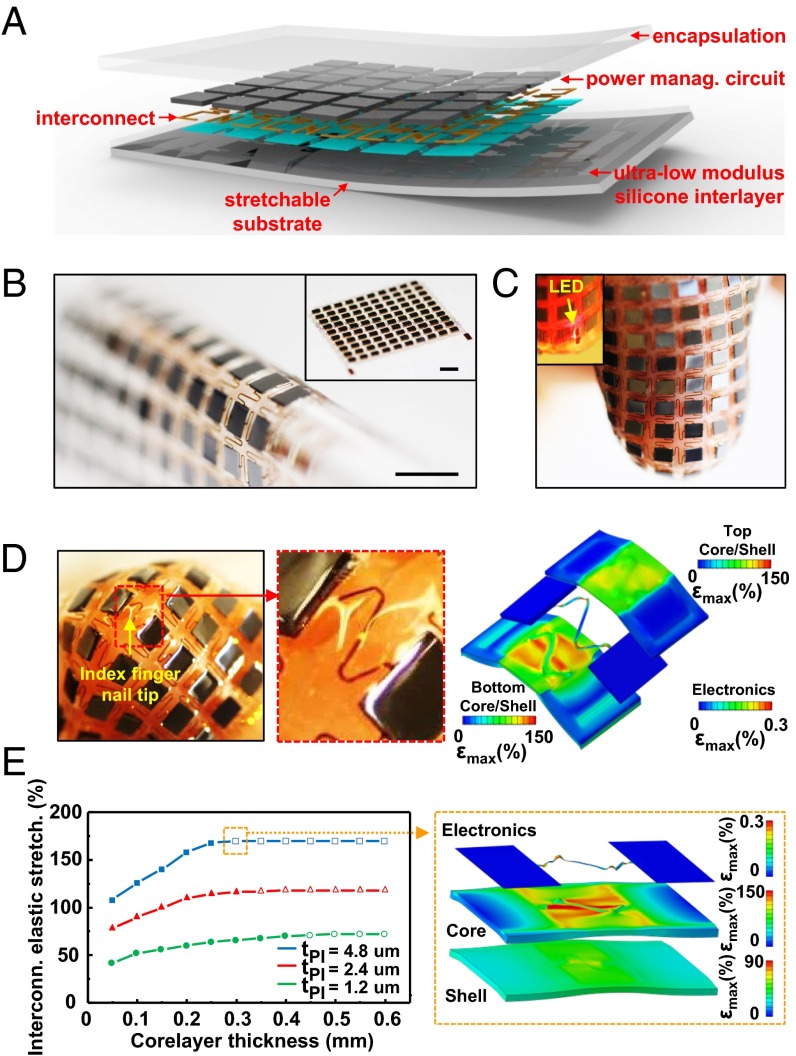
Fig. 1.
Schematic illustration, 3D-FEA results, and images of thin, soft power supply systems that incorporate arrays of miniaturized device components joined by stretchable interconnect networks and contained in two-component elastomeric matrices. (A) Exploded-view illustration of the overall architecture of a system that includes a 6 × 6 square array of components. (B) Optical image of a device that includes a 10 × 10 array of chip-scale batteries bent around a cylindrical tube with a radius of 2.5 mm. (Inset) Image of the device in planar geometry. (Scale bars, 5 mm.) (C) A photo of the device shown in B wrapped around an index finger. (Inset) Activation of a red LED while in this deformed state. (D) Enlarged view of the components and interconnects at the tip of the finger (Left), and corresponding 3D-FEA results (Right), in exploded-view format for the top shell elastomer (10 μm) coated on the bottom with the core elastomer (0.3 mm) (Top), the device components and interconnect network (Middle), and the bottom shell elastomer (0.3 mm) coated with the core elastomer (0.3 mm) (Bottom). (E) Graph of the elastic stretchability as a function of thickness of the core elastomer for three different thicknesses of the polyimide layer in the interconnect network (tPI) for the case of equal-biaxial tensile strain (Left). The hollow figures represent data points that exceed the computed limit of stretchability (Right) 3D-FEA result for the device components and interconnect network (Top), the soft core layer (Middle), and shell layer (Bottom) for the configuration illustrated by the dashed box in the graph (Left).

