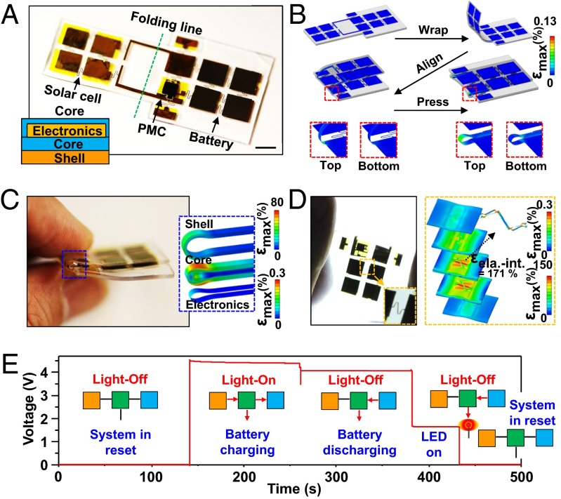
Fig. 3.
Images, 3D-FEA results, and operational data for a solar cell and battery-integrated power control system realized by folding. (A) Image of an energy harvesting/storage/supply system that includes a 2 × 2 array of 2J solar cells, a 2 × 2 array of chip-scale batteries, and a power management chip in planar geometry, before folding. (Inset) A cross-sectional illustration of the key layers. (Scale bar, 5 mm.) (B) Three-dimensional FEA results of the system at various stages of the folding process. (C) Image of the folded device and exploded-view 3D-FEA results of the maximum strain distributions near the fold for the shell elastomer (top), the core elastomer (middle), and the interconnect structure (bottom). (D) Image and exploded-view 3D-FEA results under uniaxial stretching for the top shell, top core, electronics, center core, electronics, bottom core, and bottom shell layers, from top to bottom. (E) Graph of the output voltage of the system with/without light and operation of an LED. The schematic diagrams illustrate each component of the system with colored boxes (orange, solar cell; green, power management circuit; blue, battery) and the red arrows indicate the direction of power flow.

