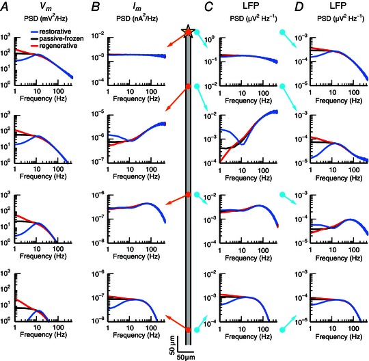
Figure 9. Membrane potential, transmembrane current and LFP for a semi‐infinite neurite with a quasi‐active conductance .

White‐noise current input (yellow star in schematic illustration in the middle) was applied to the end of a semi‐infinite neurite with a single quasi‐active conductance that was either restorative (blue), passive‐frozen (black) or regenerative (red). The simulated neurite had length 2000 μm, diameter 2 μm and intracellular resistivity cm, and the passive leak and quasi‐active conductance density were both uniformly set to 50 μS cm–2. A, membrane potential PSD () is shown at the (intracellular) positions marked by the orange circles in the schematic (at 0, 177, 531 and 973 μm distance from the input). B, as in A, but showing the transmembrane current PSD at the positions of the orange circles. C, as in A, but showing the LFP‐PSD for the (extracellular) positions marked by the cyan circles (20 μm from the neurite). D, as in C, but showing the LFP‐PSD for electrodes 300 μm from the neurite, marked by the cyan circles.
