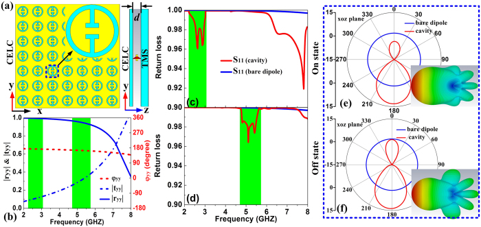
Figure 6. The schematics, reflection coefficients and resonance modes of the frequency-tunable subwavelength cavity.
(a) The schematics of the cavity consisting of CELC and TMS. (b) Scattering coefficients of the CELC, (c,d) return loss spectrum and (e,f) radiation pattern of the subwavelength cavity in the “On” and “Off” state. The lateral size of both CELC and TMS plate is 182 mm × 182 mm in the “On” state while 98 mm × 98 mm in the “Off” state. The geometrical parameters of the CELC structure are px = py = 14 mm, w1 = w3 = h2 = 1 mm, w2 = 3 mm, R = 5 mm and h = h1 = 1.5 mm.

