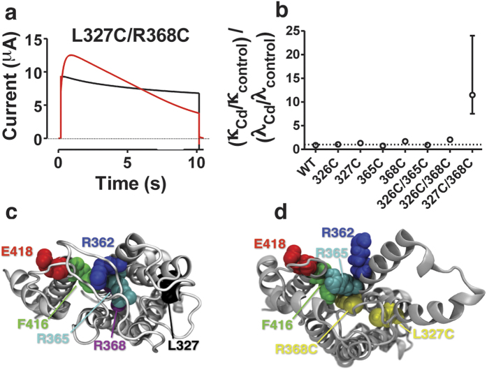
Figure 3. Interactions between S3 and S4 in the VSD affect C-type inactivation.
(a) 10 μM Cd2+ (red) inactivates L327C/R368C to a lower steady-state current. Control in black. Test step voltage = +80 mV. Holding voltage = −80 mV. pH = 7.4. (b) Quotient of Cd2+ effects on the rate constants λ and κ calculated according to Scheme I (see Methods for details) for eight different channels. Error bars are calculated from the inverse of the data. n = 3–4. (b) Top view of model of the VSD and S5 of the Shaker channel based on a crystallographic structure. (d) Top view of the model based on our experimental data. Note how a Cd2+ bridge between L327C and R368C lifts R365 (cyan) above F416 (green) without moving more positive gating charges across the central hydrophobic barrier of the VSD.

