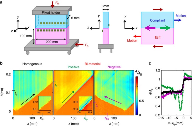
Figure 1. Experimental system and comparison of rupture profiles.
(a) Twenty rosette strain gauges (green squares) are mounted ≈2 mm above and beneath the frictional interface (left), on opposing block faces (centre). Green (purple) arrows define positive (negative) rupture propagation directions as parallel (anti-parallel) to the direction of the motion of the compliant material. (b) The real contact area, A(x,t) (normalized before nucleation at t=0), along the 200 mm quasi-1D interface. Insets: magnified sections of A(x,t). (c) A(x−xtip) measured around rupture tip locations, xtip, denoted in a; (black) PMMA on PMMA (homogenous system), Cf=0.94CR, FN=3,402 N, (green) Polycarbonate (PC) on PMMA (bimaterial system) for rupture in the positive direction, Cf=0.99CSsoft, FN=3,863 N, and (purple) leftward supershear rupture in the negative direction, Cf=0.92CLsoft, FN=3,553 N. Negative direction propagation was reversed for comparison.

