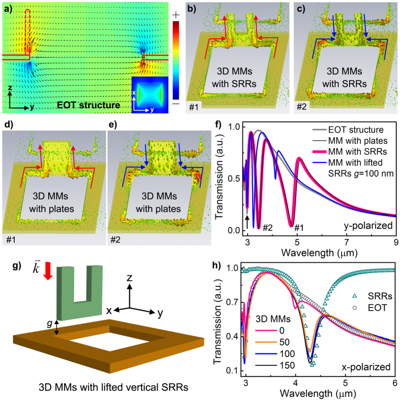
Figure 2. Modellings and simulations.
(a) Simulated E-field distribution (indicated by dark arrows) of an EOT structure (a pure metallic hole array without SRRs) in the yz plane. Ez is plotted in color. The solid red lines outline the structural profile and the dashed red lines indicate the position of the vertical structure where Ez is naturally intensified and can efficiently drive the electric current flow in the vertical structure. (Inset) Dipole-like E-field distribution of EOT structure in xy plane. (b–e) Simulated current distributions of the 3D MMs with (b,c) vertical SRRs and (d,e) vertical plates, respectively, at two distinct modes (named as #1 and #2). As noted by the arrows, Mode #1 represents an in-phase conductive current flow while Mode #2 denotes an anti-phase current flow. The similarities between (b,d), as well as (c,e), indicate the same underlying physical mechanism. (f) Simulated transmission spectra of an EOT structure, a 3D MM with vertical plates, a 3D MM with vertical SRRs and a 3D MM with lifted vertical SRRs with a gap distance of g under y-polarized light excitation. The arrow indicates the periodicity of the structural lattice. (g) Schematic of the unit cell of a 3D MM in which the vertical SRR is lifted above the EOT structure by a gap distance of g. (h) Simulated transmission spectra of an EOT structure, an SRR array, and 3D MMs with different g (unit: nm) under x-polarized excitation. Structural parameters: p = 3 μm, a = 2 μm, d = 80 nm, l = 0.9 μm, h = 0.8 μm, w = 0.25 μm; width and height of the vertical plates: lp = 0.9 μm, hp = 0.8 μm.

