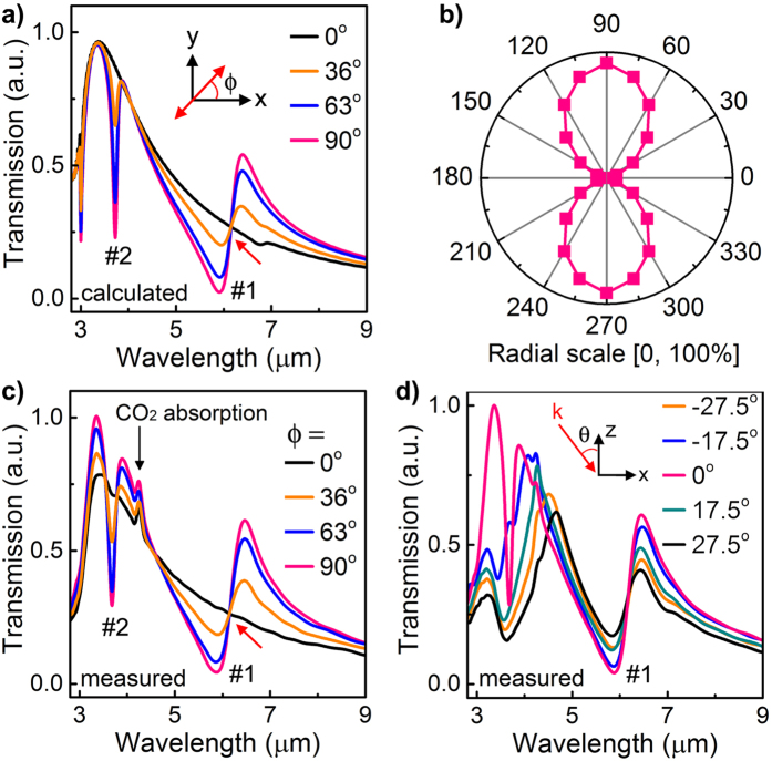
Figure 4. Prominent Fano resonances with polarization-independent spectral position.
(a) Calculated and (c) measured transmission spectra of a 3D MM under normal incidence with different polarization angle ϕ as illustrated in the inset. ϕ = 90° means y-polarized excitation. The small peaks at approximately 4.2 μm are caused by the unstable absorption from CO2 in the FTIR chamber. (b) Polar plot of the calculated suppression factor (defined as the difference in transmission between the 3D MM and EOT structure divided by the transmission of the EOT structure) at the dip wavelength of Fano resonance #1 as a function of the polarization angle under normal incidence. (d) Measured transmission spectra of the 3D MM under y-polarized excitation with different incident angle θ as illustrated in the inset. Structural parameters are the same as in Fig. 1f. The variations of dip wavelength of Fano resonance #1 in (a–d) are less than 2%, while the resonance strengths are changed due to the different excitation efficiency of SPPs under varied illumination schemes.

