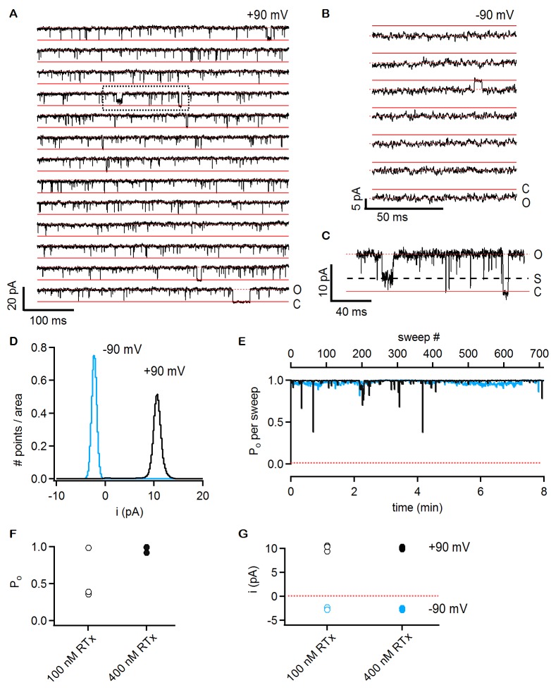
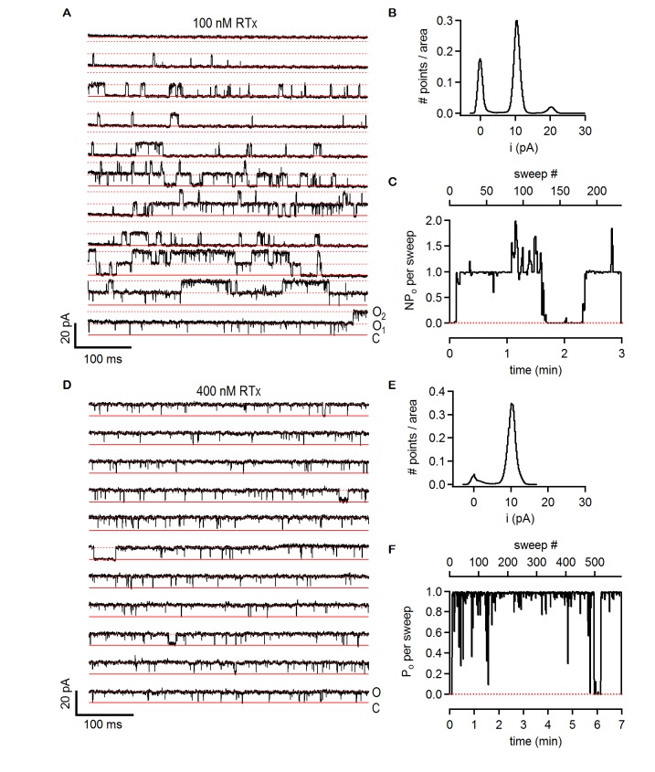
Figure 6. RTx activates the TRPV2 QM channel with high efficacy and affinity.
(A) Single-channel recordings of TRPV2 QM obtained from an inside-out patch at +90 mV in the presence of 100 nM RTx. Currents were elicited by 500 ms pulses to +90 mV from a holding potential of −90 mV applied every 200 ms. A trace without openings obtained in control solution prior to RTx application was used for leak-subtraction. The red continuous horizontal lines indicate the zero-current level (closed channel - C) and the dotted lines the current level for an open channel - O. The blue dotted rectangle denotes a portion of the recording that is shown in higher magnification in (C). (B) Single-channel recordings from the patch in (A) obtained at the holding potential of -90 mV. The continuous red lines are the zero current level (closed channel – C) and the dotted lines denote an open channel (O). (C) Magnification of the single-channel recordings in the dotted black box in (A) showing the occurrence of subconductance levels, denoted by (S) and the dashed black line. (D) Normalized all-points histograms from all recordings obtained at +90 (black) and -90 mV (blue) from the patch in (A-C). Histograms were normalized to the total area under the curve. (E) Po per sweep as a function of recording time calculated for all recordings at +90 (black) and -90 mV (blue) from the same patch in (A-D). The dotted red line denotes a Po of 0. (F) Mean Po values for TRPV2 QM at 100 nM RTx (open symbols) and +90 mV calculated from the single-channel patch in (A-E) and from two other patches with two channels each (n = 3 independent patches), together with Po values at 400 nM RTx (closed symbols) calculated from two single-channel patches and two patches containing two channels each (n = 4 independent patches). (G) Single-channel current amplitudes for the full-conductance level of an open TRPV2 QM channel in the presence of 100 nM (open symbols) or 400 nM (closed symbols) RTx at +90 (black) or -90 mV (blue) obtained from the same patches as the Po values in (F). The dotted red line denotes the zero-current level.


