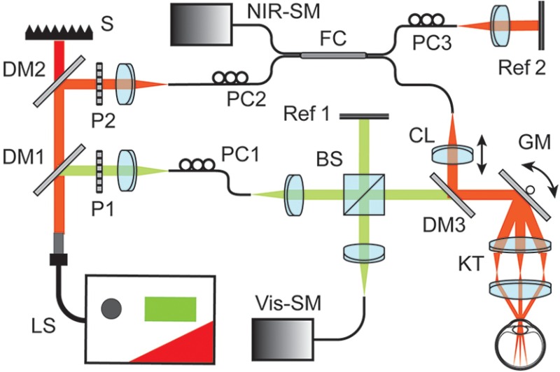
Fig. 1.
Dual-band OCT system schematic diagram. BS, beam splitter; CL, collimating lens; DM1 to DM3, dichroic mirrors; FC, fiber coupler; GM, galvanometer scan mirrors; KT, Keplerian telescope; LS, supercontinuum laser source; P, polarizer; PC, polarization controller; Ref 1 and Ref 2, reference arms; S, beam stopper; SM, spectrometer.

