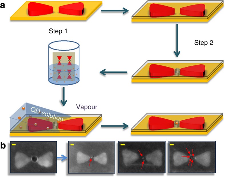
Figure 1. Construction of bowties with quantum dots in their gaps.
(a) Schematic illustration of the two-step lithography process for making holes at the centre of bowtie structures and the interfacial capillary force assisted method for driving QDs into the holes. (b) Scanning electron microscope images of bowties with one, two and multiple QDs in their gaps (from left to right). The positions of the QDs are marked by red arrows. Scale bars, 20 nm (yellow).

