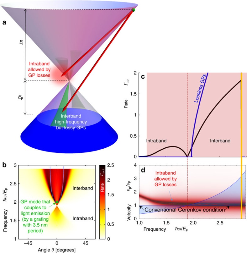
Figure 4. GP emission from hot carriers.
Caption and notations same as in Fig. 2. Unlike conventional ČE, most of the emission occurs in the forward direction with a relatively low angular spread as is shown by b. The green dot shows that GPs a particular frequency can be coupled out as light (we assume a grating with period of 3.5 nm). For the parameters used here, ČE emission occurs due to intraband transitions that are becoming allowed by the GP losses, whereas high-frequency (such as ℏω>2EF) emission occurs due to interband transitions at areas of high GP losses. The hot carrier energy Ei=1.9EF. EF as in Fig. 2.

