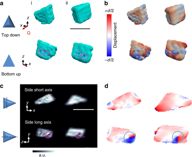
Figure 2. Bragg coherent diffraction imaging (BCDI) reconstructions.
Reconstructions of two different calcite crystals (i) and (ii), which were nucleated on carboxylate-terminated SAMs, are shown. The reconstructed crystal shapes from BCDI amplitude measurements are shown in a, where these are viewed from the directions indicated. The surface cusps, which appear on the bases of both crystals, are circled. (b) The projected displacements (−d/2 blue lattice dilation and +d/2 red lattice contraction) of the crystals. (c) Sections through the electron density maps and (d) sections cut through the displacement maps, where these made through the centres of the crystals, normal to the substrate. The surface cusps (magenta circle) and areas of spiral displacement (cyan circle) are highlighted. The beam direction is along the z axis, with the y axis vertical, while the sample/substrate is located at a set scattering angle towards the beam direction (z) with Q the scattering vector. Scale bar, 1.8 μm.

