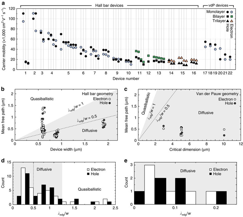
Figure 6. Mobility and mean-free path statistics.
(a) Room temperature field effect carrier mobility plot for all the devices (Hall bar and van der Pauw) in this study. (b) Plot of electron and hole mobility for all monolayer Hall bar devices. Quasiballistic (λmfp≥w) and diffusive (w>λmfp) regimes are indicated by the white and grey regions, respectively. Note that 60% of our narrow channel devices have a calculated mean-free path larger than w/2 (dashed line), a clear indication of transport affected by boundary scattering17. (c) Plot of electron and hole mean free path for all monolayer van der Pauw devices. Quasiballistic (λmfp≥w) and diffusive (w>λmfp) regimes are indicated by the grey region. The average mean-free path is 450±170 and 420±140 nm for holes and electrons, respectively. (d) Histogram of monolayer electron and hole mean free path for all Hall bar devices. (e) Histogram of monolayer electron and hole mean free path for all van der Pauw devices.

