Fig. 3.

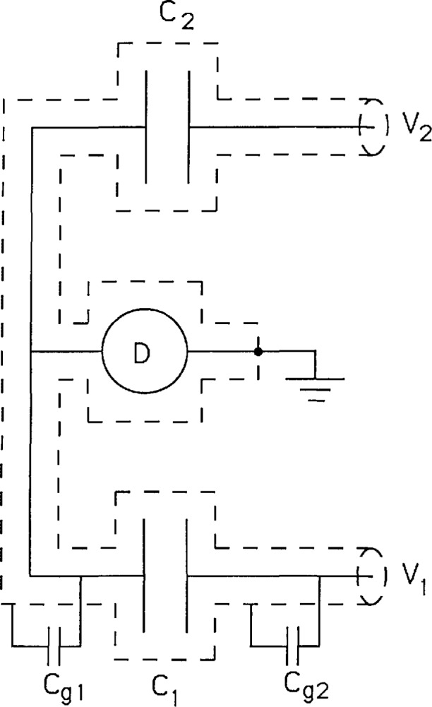
Circuit showing half of a bridge used to compare capacitors C1 and C2. The potentials V1 and V2 are usually supplied by a precision transformer. The effect of stray capacitances Cg1 and Cg2 are discussed in the text.

Circuit showing half of a bridge used to compare capacitors C1 and C2. The potentials V1 and V2 are usually supplied by a precision transformer. The effect of stray capacitances Cg1 and Cg2 are discussed in the text.