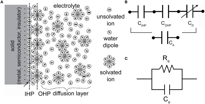
Figure 2.
Electrode-electrolyte interface and equivalent electrical circuits. (A) Schematic representation of an electrode-electrolyte interface. (Adapted from Bockris and Reddy, 1977). (B) Series of three capacitors (corresponding to the IHP, OHP, and diffuse-layer) which models the charge distribution at the interface. (C) Electrical circuit of an electrode-electrolyte interface. Re is the charge-transfer resistor and Ce is the double-layer capacitor.

