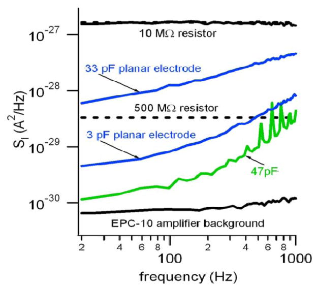
Fig. 3.
Larger electrodes have a larger current PSD, but the noise does not originate from capacitive loading of the potentiostat. Lower black trace is the open-input noise of the EPC-10 potentiostat (50 GΩ feedback resistor) whereas the green trace is the PSD when the input of the amplifier is loaded with a 47 pF capacitor. The upper blue trace is the PSD from a ~430 μm2, 33 pF ITO electrode whereas the lower blue trace is from a ~39 μm2, 3 pF ITO electrode. The 33 pF electrode has much higher noise than the 47 pF discrete capacitor which demonstrates that capacitive loading of the amplifier is not the dominant noise source. The dashed lines depict the theoretical thermal noise of 10 MΩ and 500 MΩ resistors for comparison.

