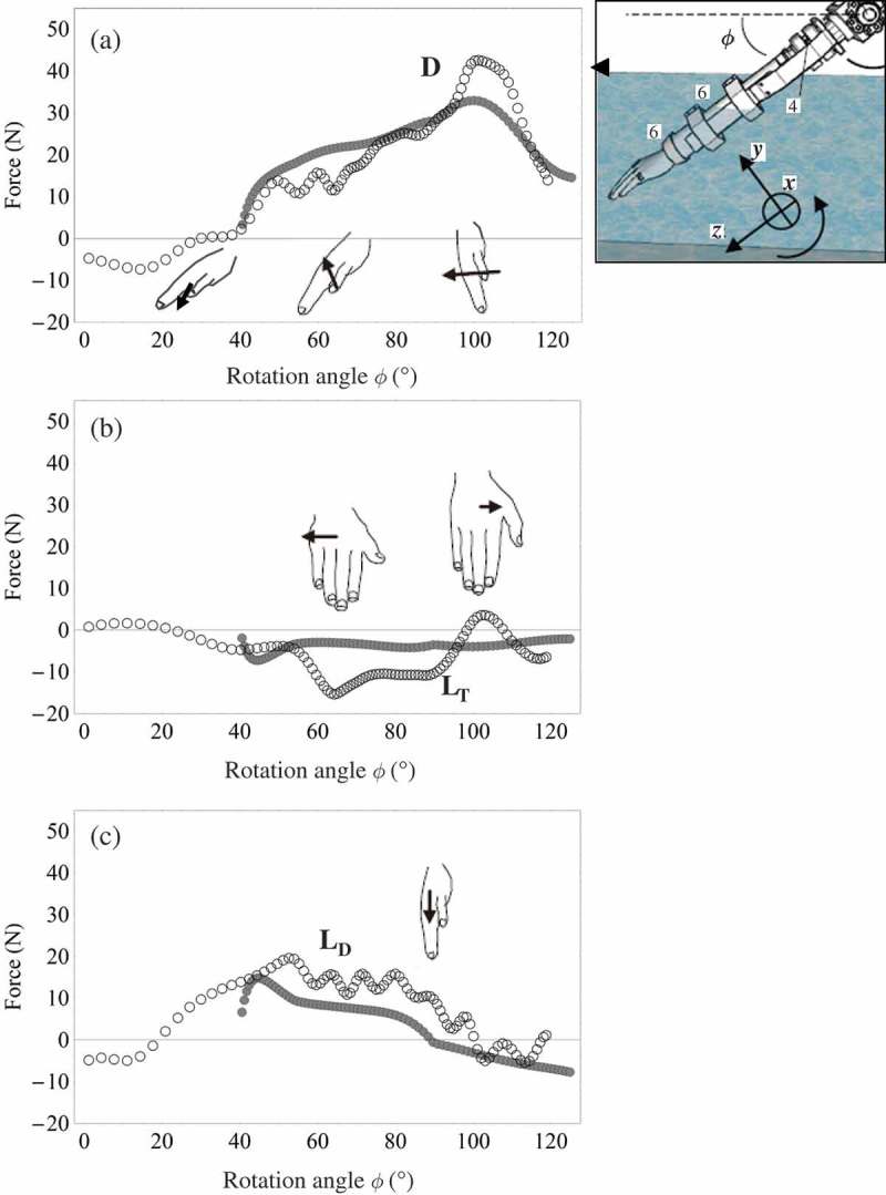
Figure 12.

(a) Drag force acting on the hand (D); (b) transverse lift force acting on the hand in the x direction (LT); and (c) lift force in the dorsal direction acting on the hand perpendicular to the drag and transverse lift forces (LD) in the flowing flume set at 1.5 m · s–1. In (a), (b) and (c), the empty circles (○) represent hydrodynamic forces on the hand measured during acceleration, and the filled circles (●) represent hydrodynamic forces calculated for a non-accelerating hand. The hands in the figures show orientations, while the arrow with the hand represents the direction of the hydrodynamic force acting on the hand at the respective φ (Kudo et al., 2013).
