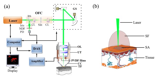
Fig. 1.
Schematic of the photoacoustic dermoscopy system. (a) Instrument layout showing the optical paths and electrical connections. DAS, data-acquisition system; OFC, optical filter and collimator; NDF, neutral density filter; PD, photodiode; BS, beam splitter; CL, convex lens; GS, galvanometer scanner; OL, objective lens; UT, ultrasound transducer; PVDF films: polyvinylidene fluoride films; CC, coupling cup; TF, transparency films. (b) Schematic of photoacoustic scanning acquisition. SF, sound field; SA, scanning area.

