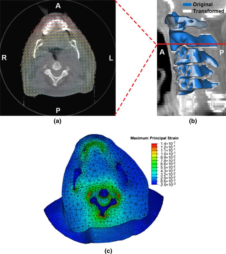
Fig. 4.
Results of the FE analysis under a combined set of force and displacement boundary conditions: a the displacement vector field overlaid on an axial plane of the cone-beam CT image volume on which the model was constructed (scaled), b the original and transformed geometries of the cervical vertebrae (C1–C5) with the level of the CT slice shown in a annotated, c the maximum principal strain field shown on the deformed geometry (A anterior, P posterior, L left, R right)

