
Figure 4.
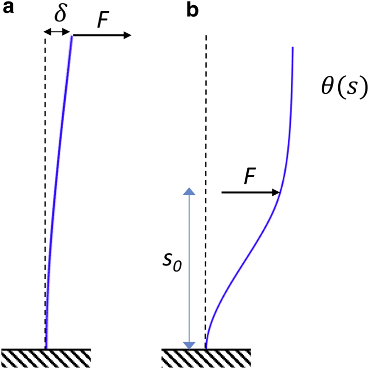
Mathematical models of the tip compliance and counterbend experiments. (a) A load, F, applied at the tip produces a deflection, δ. The tip compliance C = δ/F depends on both intrinsic flexural rigidity EI and shear stiffness ks. (b) A load, F, applied near the midpoint (at s = s0) produces a bend-counterbend shape described by the angle θ(s), which depends on the load amplitude, the location of the load, and on the ratio β2 = ks/EI. To see this figure in color, go online.