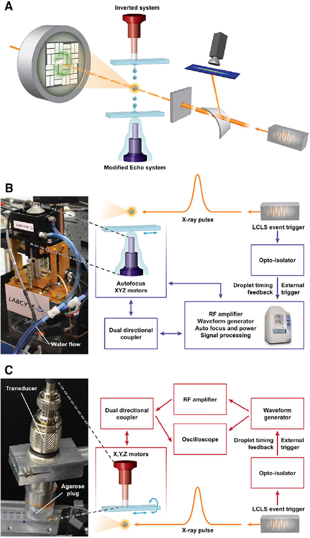
Figure 1. Acoustic Injection for SFC.
(A) Schematic overview image shows incoming X-ray pulses passing first through a bent transmissive silicon crystal, deflecting a portion of each pulse for spectrographic recording. The pulses arrive at the interaction region concurrent with a crystal-containing droplet. In the inverted system, the droplet is ejected downward out of a multiwell microplate. The modified Echo system is configured to eject droplets upwards out of a multiwell microplate. Diffraction patterns were recorded 108 mm downstream of the interaction point by a Cornell-SLAC pixel array detector. The three drops are meant to illustrate the repeatable nature of the ejection process and are not to scale.
(B) Detail for the modified Echo system in which the acoustic injector (photo, left) was controlled through an “umbilical cord” with electrical and water connections to the Echo instrument.
(C) Detail for the inverted system wherein an agarose plug maintained the acoustic connection between the transducer and the inverted microplate well (photo, left). Illustration courtesy Tiffany Bowman, BNL. See also Figure S1.

