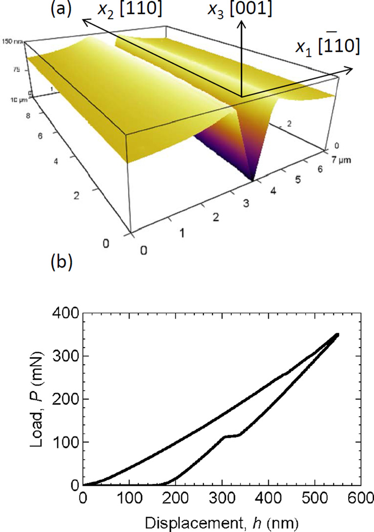
Fig. 1.
(a) SEM image of the analyzed wedge indentation and adjacent deformation field. The image is foreshortened in the vertical direction along the indentation long axis by a factor of 2.5. (b) AFM-obtained three-dimensional rendering of the residual deformation profile of the central section of the wedge indentation. The x1–x2–x3 coordinate system used is indicated. (c) The load-displacement behavior observed during indentation.

