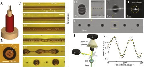
Fig. 6.
Broken azimuthal symmetry in a spherical particle enables polarization-sensitive scattering. (A) Schematic of the fiber structure that produces strings of high-index contrast nanoparticles within a photonic particle. (B) Optical transmission micrograph of the fiber cross-section. (C) Optical transmission micrographs capturing the fiber breakup dynamics during thermal treatment. First, the four G2 [Ge1.3(As2Se3)98.7] inner threads break up in parallel strings of smaller particles, and then the polymer cladding P (PES) and thin glass shell G1 (As2S3) subsequently break up. Time is indicated in the Top Left corner of each panel. (D) Optical transmission micrograph through a microparticle produced in C. (E) Transmission optical micrograph of a section of fiber containing a necklace of 3-μm–diameter particles with the same structure as in D. (F) Higher-magnification micrograph of a section of the fiber in E. White light is used in imaging, whereas a green laser is imaged in reflection (the horizontal white line) and scatters strongly parallel to the axis along which the internal high-index nanoparticles are aligned. (G) A micrograph of a single particle from F with combined laser and white-light scattering. (H) Micrograph of laser light scattering from a single particle (white light turned off). The yellow circle is a guide to the eye and corresponds to the particle surface. (I) Schematic depiction of the optical arrangement for measuring the polarization-dependent scattering. The yellow beam indicates the transmitted white light used to align the sample, whereas the green one corresponds to the laser radiation used to measure the backscattering. HWP, half-wave plate; BS, beam splitter; S, source; D, detector. (J) Sinusoidal modulation of the integrated scattered intensity (squares) as a function of incident polarization angle. The maximum occurs when light is polarized along the direction of the internal nanoparticle strings. Squares are the data, and the solid line is a sinusoidal fit.

