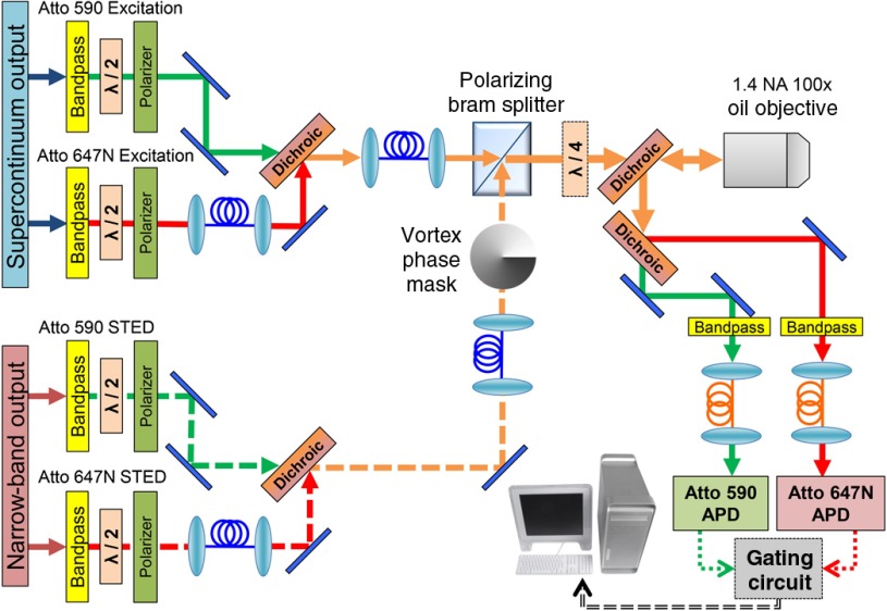
Fig. 2.
Optical schematic for the two-color STED microscope. Each beam is bandpass filtered and then sent through a half-wave plate and polarizer in succession, allowing clean polarization and individual power control. Excitation beams are combined into one polarization maintaining (PM) fiber and the STED beams are combined into another PM fiber using dichroic mirrors. STED beams pass through a vortex phase plate to generate a donut shape at the focus of the objective. A polarizing beamsplitter combines the beams and a quarter-wave plate makes the polarization circular. The beams are sent through a custom dichroic, which passes the four STED/excitation laser beams and reflects the fluorescence emission. The two emission bands are then separated using another dichroic beamsplitter. Fluorescence is focused into a multimode fiber that is coupled to an APD. The signal from the APDs goes through the custom gating circuit to counter inputs on the data acquisition (DAQ) board in the computer. The same DAQ board also controls the scanning of the piezo stage to acquire an image.

