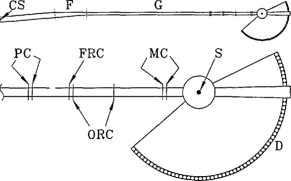
Fig. 15.

Simplified plan view of the disk chopper spectrometer. The upper diagram shows the overall setup of the instrument including cold source (CS), filter (F), and guide (G). The lower diagram shows the choppers, the sample position (S), and the detectors (D); PC, ORC, FRC, and MC denote pulsing, order removal, frame removal, and monochromating choppers, respectively. The width of the guide, the separation between closely spaced choppers, and the angle between initial and final guide sections, have been exaggerated for clarity. The filter is a tapered section of guide, ∼7 m long, that redirects slow neutrons (through 0.25°) whereas fast neutrons and γ rays are removed from the beam because they are not reflected. It is located within the wall between the reactor confinement building and the guide hall.
