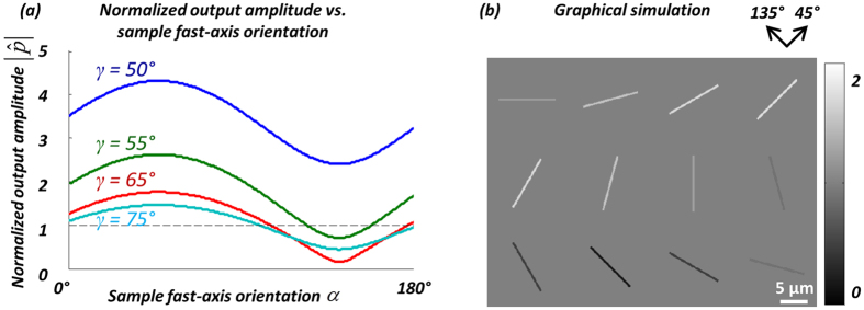
Figure 4.
(a) Optimization of the orientation angle of the linear polarizer (γ). The normalized output amplitude  is plotted as a function of the sample fast-axis orientation, α, for different linear polarizer orientations (γ = 50°, 55°, 65°, 75°). (b) The simulated normalized output images of MSU crystals at varying orientations, using γ = 65°. The MSU crystals are simulated as cylinders with a birefringence of |Δn| = 0.1, diameter of 0.5 μm, length of 10 μm, and the fast axis is along the long axis of the crystals.

