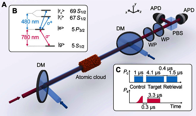
Fig. 1. Experimental procedure.

(A) Scheme of the experimental setup. Signal light (red) illuminates an atomic gas. Two additional beams (blue) provide EIT-coupling light, one copropagating and the other counterpropagating the signal light. Dichroic mirrors (DMs) overlap and separate the beams. The polarization of transmitted signal light is measured using wave plates (WPs), a polarizing beam splitter (PBS), and avalanche photodiodes (APDs). (B) Level scheme. The 780-nm signal light couples states |g〉 = |5S1/2, F = 2, mF = −2〉 and |e〉 = |5P3/2, F = 3, mF = −3〉. The 480-nm EIT-coupling light couples states |e〉 and |r〉 = |nS1/2, F = 2, mF = −2〉, with nc = 69 and nt = 67 for control and target pulse, respectively. (C) Timing sequence of input powers of coupling light Pc and signal light Ps. The control pulse is stored in the medium, the target pulse propagates through the medium picking up a π phase shift if a control excitation was stored, and, eventually, the control excitation is retrieved.
