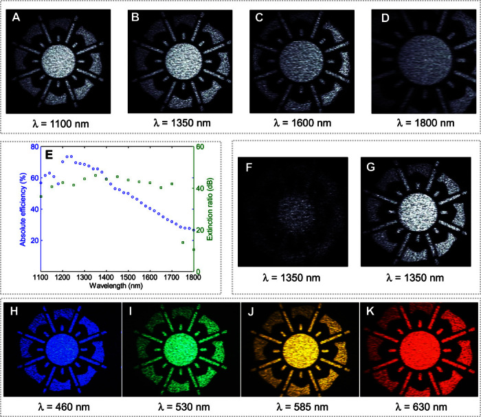
Fig. 3. Broadband phase distortion–free hologram.

(A to D) Images generated when the hologram is illuminated with NIR light. (E) Absolute efficiency and extinction ratio (ER) as a function of wavelength. The drop in ER is due to the significant drop in the efficiency of the imaging camera at longer wavelengths. (F and G) Images corresponding to a hologram in which the IYL logo phase distribution is added to that of a Fresnel lens with a 2-cm total shift of the reconstruction plane. (F) Image captured under the same measurement conditions of (A) to (D). This image is blurry because the Fresnel lens phase profile encoded in the hologram moves the image plane 2 cm forward along the propagation direction. (G) The same image appears correctly in focus when the camera is moved 2 cm along the propagation direction. (H to K) Images generated by the hologram in the visible range. These images were captured by a color charge-coupled device camera.
