. 2016 Jun 2;5:e14618. doi: 10.7554/eLife.14618

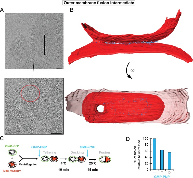
Figure 6. Stages of outer membrane fusion.

(A and B) Cryo-ET of docked mitochondria with partially fused outer membrane. (A) Slices through tomographic volume; scale bars 100 nm. The red circle highlights the region of outer membrane fusion. (B) 3D rendering. Two mitochondria are joined by one continuous outer membrane (red). The inter-membrane spaces are connected by a toroid pore of 40 nm diameter. (C and D) Fluorescence microscopy of in vitro outer membrane fusion. GMP-PNP was added at the beginning (tethering, T) or at the end (docking, D) of the 10 min incubation period.

DOI: http://dx.doi.org/10.7554/eLife.14618.016

Figure 6.

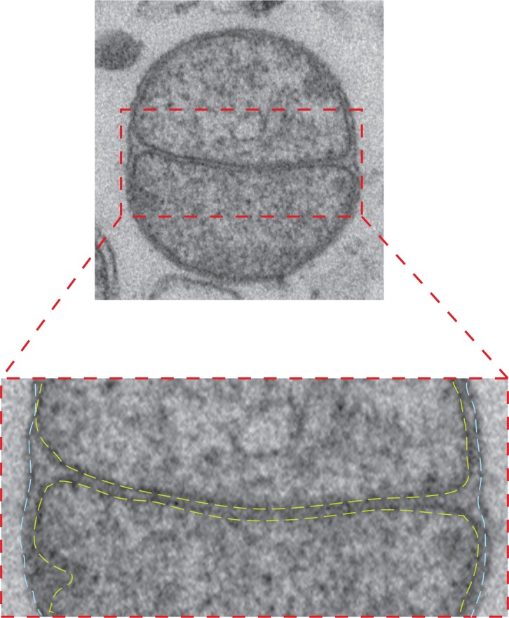
Figure 6—figure supplement 1. Intermediate with fully fused outer membrane.

Figure 6—figure supplement 1.

Top: TEM micrograph of an intermediate with completely fused outer membrane, obtained by in vitro outer membrane fusion of mitochondria isolated from wild-type cells. Lower panel: Zoom of the contact region shows the apposition of inner membranes (yellow dashed lines) and continuous fused outer membrane (blue dashed lines).
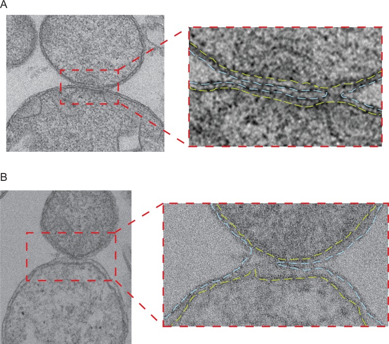
Figure 6—figure supplement 2. Intermediates with partially fused outer membranes.

Figure 6—figure supplement 2.

(A and B) Left: Electron micrograph of two pairs of attached mitochondria with partially fused outer membranes in stained thin plastic sections of wild-type mitochondria obtained as for Figure 6—figure supplement 1. Right panels: Zoom of the contact region shows the continuous inner membranes (yellow dashed lines) and the cross section through the toroid pore opening at the right (A) or the left (B) edge of the contact region of outer membranes (blue dashed lines).