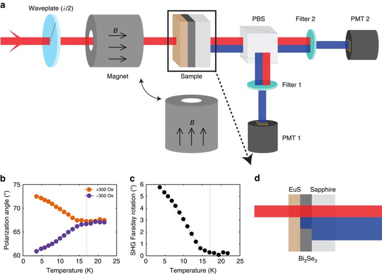
Figure 1. SHG Faraday rotation.
(a) Experimental set-up. PBS, polarizing beam splitter; PMT, photomultiplier tube. Rotation of the SHG polarization plane was calculated by using two PMTs that separately measure SHG intensities of s and p polarizations, respectively. Either an in-plane or an out-of-plane magnetic field was applied to the sample. (b) Output SHG polarization angle and (c) SHG Faraday rotation angle plotted against temperature for the 7 nm (EuS)–7 QL (Bi2Se3) sample. (d) In EuS–Bi2Se3 heterostructures, surface SHG is generated from the EuS–Bi2Se3 and Bi2Se3–sapphire interfaces. In a and d red and blue lines correspond to the laser beams of ω and 2ω frequencies.

