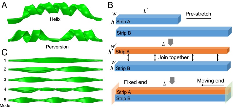
Fig. 1.
Illustration of the bistrip model. (A) A typical perversion arising in an otherwise uniform helix (Upper) by controlling the boundary condition. (B) Illustration of the bistrip model we used in the simulation. Strip A has the same cross-section as strip B but shorter length in the initial state. Strip A is stretched and glued to strip B; both strips have the same length. One end of the bistrip system is fixed whereas the other end is allowed to translate but forbidden to rotate. (C) The first five buckling modes from eigenvalue buckling analysis.

