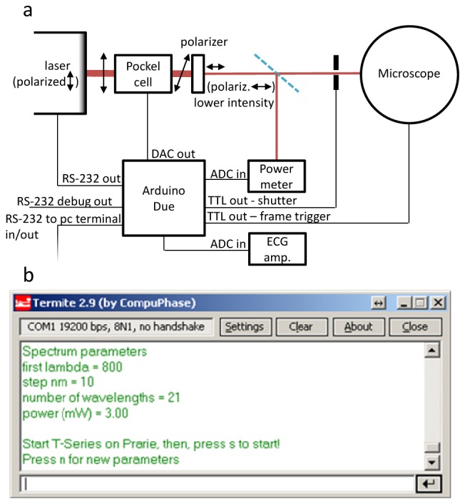
Fig. 1.

(a) A sketch of both analog and digital connections between the Arduino Due and the other devices of a typical two-photon microscope. Dark red lines represent the laser beam (with intensity roughly proportional to their thickness), and double arrow represents its polarization direction (with horizontal direction actually meaning out of plane polarization). (b) A screenshot of the RS-232 text-based user interface, in which the parameters (first wavelength, step, number of wavelengths in the spectrum, power of the laser beam) are passed to the Arduino Due.
