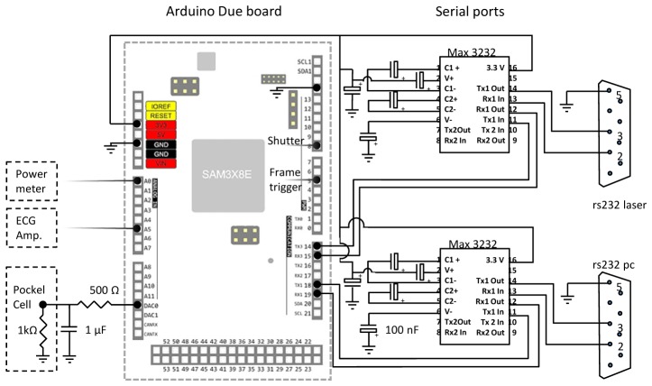
Fig. 2.
Electronic scheme of the digital connections between the Arduino Due and the RS-232 ports to pc and laser (pin 14-15-18-19 of the Arduino board), to the beam shutter (pin 8) and to the frame trigger of the microscope (pin 5). Analog ports are connected to the power meter (ADC 0) and to the Pockels cell (DAC 0). The latter uses a voltage divider and a low pass filter to avoid any damage on the Pockels cell electronics. All electrolytic capacitors connected to the Max 3232 ICs are 0.1 μF / 10V.

