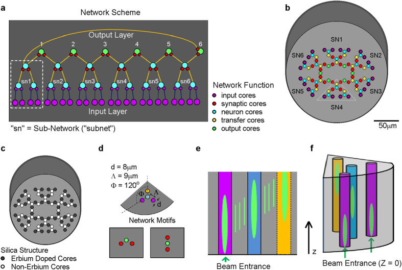
Figure 2. Architecture of a feed-forward network with lateral connections in the output layer.
(a) The network may be subdivided to six subnets (SN), where the output of each is shared by two adjacent output neurons. (b) The multi-core fiber implementation; 90 silica cores are embedded in cladding, each core has a functional role and input cores serve also as synaptic cores. (c) Amplification scheme: 48 of the cores are erbium doped (dark gray) and serve as controlled amplifiers. (d) The microstructure of network motifs: the three types of building blocks that are used in the network. (e) Two-dimensional scheme depicts the tangential signal transduction; coupling between neighboring cores simulates the transfer of signals in the network while propagation along z-axis simulates the passage of time. (f) Three-dimensional illustration demonstrates simultaneous coupling and convergence of two cores to one.

