
Figure 6.
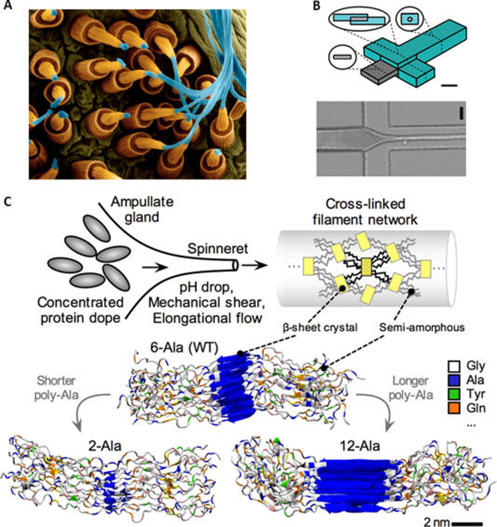
Fiber formation from spider silk proteins upward: (A) Natural. Copyright Dennis Kunkel Microscopy, Inc./Visuals Unlimited/Corbis. (B) Bioinspired microfluidic process, which used microfluidic for silk worm silk. (Adapted with permission from ref 103. Copyright 2011 American Chemical Society.) Similar principles apply to the production of spider silk. (C) Detailed molecular view. (B) Regenerated silk fibroin (RSF) solution flows through the central channel while acidic poly(ethylene-oxide) (PEO) solution flows through the side channels. As these solutions combine and flow in the device, the PEO solution surrounds the silk solution, focusing hydrodynamic silk solution stream, causing a narrowing of fiber diameter, permitting diffusion of hydrogen ions into the silk to generate RSF fiber. The schematic of the device (B left side) features a scale bar 400 um, and the microscopic image (B bottom) of the actual spinning process has a scale bar 200 um, where RSF solution inlet is the left channel, PEO solution inlet for top/bottom channel and silk stream outlet is right channel. (C) In the process of silk spinning, a combination of chemistry and shear flow transform the concentrated protein dope into a network cross-linked by aligned crystalline overlaps held by aligned hydrogen bonds. Lower images reprinted from ref 180. Copyright 2011 Wiley. The image also explains the effect the amino acid sequence has on the molecular structure of the silk fiber, where the number of alanine amino acid repeats controls the size of beta-sheet nanocrystals at the nanometer length-scale.