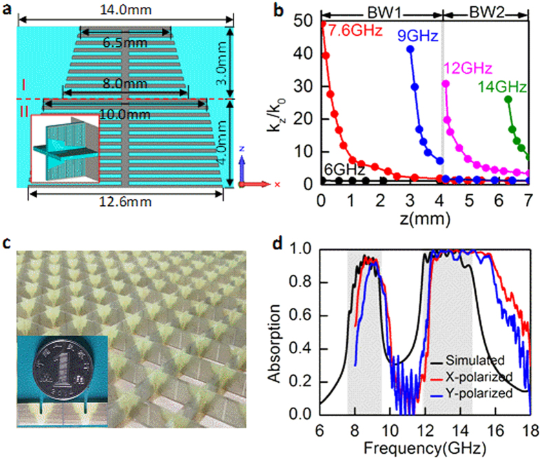
Figure 6. Spatial k-dispersion engineering for frequency-selective broadband absorption.
(a) Design of the unit cell of a frequency-selective broadband absorber. The groove depth decreases linearly from bottom to top with an abrupt change at z = 4 mm. The panel of unit cell in the x-z plane is divided into the top region I and the bottom region II by the interface line. Inset is the three-dimensional schematic of the unit cell. (b) Spatial k-dispersion relations at different frequencies. Two theoretical bandwidths termed as BW-1 and BW-2 are marked in the top axis. (c) Photograph of the fabricated absorber. (d) Comparison between the absorption spectra respectively simulated and measured from the fabricated sample. Two theoretical bandwidths of 7.6–9.5 GHz and 11.9–14.7 GHz are highlighted by gray regions.

