Figure 1.
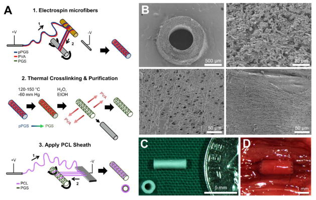
TEVG fabrication and structure. A. Schema of the fabrication process. A1–Electrospin microfibers. A polymer solution containing pPGS (blue) and PVA (red) is infused through a positively charged spinneret to form a polymer jet that deposits onto a plastic rod (1) and then is drawn onto a rotating stainless steel mandrel (2). The result is a mandrel coated with microfibers of a pPGS-PVA blend (right). A2–Thermal Crosslinking and Purification. Microfiber coated mandrels are thermally crosslinked to convert pPGS (blue) into PGS (green). PGS-PVA microfibers are then purified in water and ethanol to remove the PVA, which yields a microfibrous tubular core composed primarily of PGS (right). A3–Apply PCL Sheath. A PCL solution (purple) is infused through a positively charged spinneret to form a polymer jet that initially deposits onto an aluminum plate anode (1) and then is drawn onto the rotating PGS core (2). The result (right) is a composite graft consisting of an electrospun PGS microfiber core (green) and an electrospun PCL fiber sheath (pink). B. Graft microstructure visualized by Scanning Electron Microscopy. Top left–Transverse cross-section at 50x. Top right–Transverse cross-section of the electrospun PGS core at 1000X shows a network of microfibers with space between some fibers and limited fusion between others. Bottom left–Luminal surface of graft at 400X magnification. Fused fibers create a smooth surface in some regions, but frequent gaps in fusion provide access to the space within the PGS core. Bottom right–Abluminal view of the graft at 400X magnification shows coverage with the PCL sheath, consisting of microfibers and nanofibers. C. Macroscopic view of a finished graft prior to implantation; the graft is pictured next to an American dime for size comparison. Inset–transverse view of finished graft. D. In situ view of a TEVG conducting blood flow on the day of implantation.

