Abstract
We demonstrate magnetophoretic conductor tracks that can transport single magnetized beads and magnetically labeled single cells in a 3-dimensional time-varying magnetic field. The vertical field bias, in addition to the in-plane rotating field, has the advantage of reducing the attraction between particles, which inhibits the formation of particle clusters. However, the inclusion of a vertical field requires the re-design of magnetic track geometries which can transport magnetized objects across the substrate. Following insights from magnetic bubble technology, we found that successful magnetic conductor geometries defined in soft magnetic materials must be composed of alternating sections of positive and negative curvature. In addition to the previously studied magnetic tracks taken from the magnetic bubble literature, a drop-shape pattern was found to be even more adept at transporting small magnetic beads and single cells. Symmetric patterns are shown to achieve bi-directional conduction, whereas asymmetric patterns achieve unidirectional conduction. These designs represent the electrical circuit corollaries of the conductor and diode, respectively. Finally, we demonstrate biological applications in transporting single cells and in the size based separation of magnetic particles.
Keywords: single cell, magnetism, 3-dimensional field, microfabrication, microfluidics, particle separation
Introduction
One of the main goals of lab-on-a-chip systems is to control the transport of objects suspended in fluids, ranging from cells to small molecules [1-4]. The ability to organize single particles and cells into arrays hold great promise for analyzing the rare, but important, cellular events, which are typically overlooked by the ensemble averaging approaches of traditional biological assays. Many approaches have been investigated to transport objects in microfluidic systems based on locally applied electric, magnetic, acoustic, optic, and hydrodynamic flow fields [5-22]. Some of these approaches have been commercialized and used for rare cell separation and analysis [5-6]; however, there are few examples of integrated systems which can emulate the higher level functions of computer circuits and automate the control of cells and particles in a highly scalable manner.
Previously, we demonstrated a novel architecture for organizing and storing single particles and cells in microfluidic environments in a manner that resembles a computer random access memory (RAM) [20-22]. The building blocks in this memory are designed to imitate the functionality of circuit elements, such as conductors, diodes, capacitors, and transistors. For example, when magnetizable particles are exposed to lithographically fabricated magnetic patterns and an in-plane rotating magnetic field, they are transported across the substrate in a manner similar to Ohm’s law of electrical circuits. However, the in-plane magnetizing field used in prior works can have the undesirable effects of forming clusters when two particles come into contact. As the clusters nucleate and grow, they sometimes stop moving due to their large size and mismatch with respect to the track geometry, which hinders proper functioning of the circuit.
To avoid this potential problem and maintain the versatility of the particle transport system, here we introduce an additional vertical bias field to induce weak repulsion and inhibit cluster formation. Unfortunately, this 3-dimensional magnetic field prevents particles from transporting across the previously studied magnetic track geometries [20-22]. The fundamental problem originates from the rotational symmetry of dipolar systems exposed to in-plane rotating magnetic fields, in which the dipoles cannot distinguish between the north and south poles of the magnetic pattern. In the absence of a vertical field, the magnetized objects are able to periodically switch between the north and south poles without penalty, which allows them to be transported across linear arrays of serially connected disks. This equal preference for two positions on the magnetic pattern (i.e. degeneracy) leads to additional difficulties in synchronizing particle motions in the global clock cycle.
These observations have led us to think more philosophically about the types of pattern curvatures that induce linear translation of potential energy minima in the presence of a 3-D magnetic driving field. If all of the geometries have positive curvature, like the previously studied systems, then the energy minima translate in closed loop trajectories. If instead, the track geometry consists of alternating sections of positive and negative pattern curvature, we hypothesized that rectified particle transport could be achieved.
Many of these ideas are borrowed from magnetic bubble technology, which was explored in the 1970’s and 1980’s to perform logic operations and store digital information [23-30]. In this technology, a strong vertical field is used to create small domains of magnetization (i.e., magnetic bubbles) in iron garnet films. These bubbles, which represent bits of data, were locally trapped by overlaid magnetic patterns and moved along desired directions with a time-varying external field. A similar idea has also been used recently to manipulate ferrofluid droplets immersed in oil, which have geometric similarity to the cylindrical domains of magnetic bubble films [31]; however, it was far from clear whether this approach would work for solid discrete particles, such as magnetic beads and magnetized cells inside microfluidic systems.
Here, we demonstrate an approach to manipulate colloidal objects on top of patterned permalloy films exposed to a time-varying 3-dimensional magnetic field. Compared with prior investigations of magnetic bubble technology, there are fundamental differences in the operating conditions of magnetophoretic conductors for transporting micron-sized physical objects. First, owing to the increased mechanical drag of microfluidic environments, the operating frequencies of this system (Hz) are orders of magnitude slower than the transport of bubbles domains inside iron garnet films (KHz). Second, due to fundamental differences in the geometry of the mobile components, the 3-D magnetic field profiles required to transport spherical particles are substantially different from the cylindrical domains in magnetic bubble technology. We also discovered new types of magnetic track geometries, which are more adept at conducting magnetic particles.
In the following sections, we demonstrate several conductor geometries which can be used to transport magnetic particles in a conical magnetic driving field (i.e., a static vertical field superimposed with a rotating in-plane field). One particular geometry, hereafter referred to as the “drop-shape” pattern, is shown to have the ability to manipulate smaller objects than other patterns described in the magnetic bubble literature. The transport properties of magnetic beads and magnetically labeled cells on the drop-shape pattern are studied as a function of frequency and cone angle. Finite element simulations also confirm that rectified motion occurs over a specified range of cone angles for this geometry. Next, we evaluate track geometries that have unidirectional transport properties, which act as corollaries to electrical diodes. For one sense of field rotation, particles move in open trajectories; however, when the direction of field rotation is reversed, the particles move in closed orbits. Finally, we show the ability to manipulate magnetically labeled cells and separate different sized particles, by controlling the cone angle and magnitude of the external magnetic field.
Material and Methods
Though a detailed fabrication process is explained elsewhere [22], in brief, magnetic track patterns were fabricated on silicon wafers (University Wafer, Boston, MA, USA), using conventional photolithography (Karl Suss MA6/BA6 mask aligner), followed by electron beam evaporation (Kurt Lesker PVD 75) of 5nm/100nm stacks of Ti/ Ni80Fe20. After lift-off, the chip was coated by a 250nm thick layer of SiO2 (PECVD, Advanced Vacuum Vision 310). Finally, to reduce the adhesion of particles and cells to the substrate, a 50nm thick coating of “non-fouling” POEGMA brushes were deposited on top of the chip. The protocol for achieving the POEGMA functionalization is described elsewhere [32].
Magnetic transport experiments employed three types of magnetic beads (Spherotech CM-50-10, FCM-8056-2, and CM-150-10, with mean diameters of 5.7-μm, 8.4-μm, and 15.6-μm, respectively). The transport properties of human CD4+ T-cells were also studied by magnetically labeling them with anti-CD4 antibody conjugated magnetic nanoparticles (StemCell Technologies, Vancouver, Canada), with cell isolation purity confirmed by flow cytometry. Experiments on magnetic beads and cells were conducted in de-ionized water and phosphate-buffered saline (PBS), respectively. The rotating field was applied by a custom microscopy stage fabricated with a 4-pole structure in an iron plate (McMaster Carr) wrapped with magnet wire (20AWG). Another magnetic coil placed underneath the stage was used to create the vertical field. All magnetic coils were powered by programmable power supplies (Kepco BOP 20-5M), and controlled by a customized LabVIEW program (National Instrument). A Leica DM LM microscope with a Retiga 2000R video camera was used to record bead (called particle, in the rest of manuscript) and cell motion.
Due to the complicated magnetic track geometry, it is not possible to obtain analytical expressions for the magnetic field distribution. Instead, finite element methods (FEM) (Ansoft Maxwell 15.0) were used to simulate the magnetic fields and create 2-D dipolar energy landscapes. Since the magnetic patterns are assumed to be linearly magnetizable, the computational analysis was simplified by simulating the magnetic fields in only three cases, in which the external field was applied in the x-, y-, and z-directions, respectively. By linear combination of these three cases, it is possible to create an arbitrary 3-D magnetic field profile.
Results
Bidirectional conductors
The locations of the local field maxima in linear magnetizable systems occur at positions where the outward normal of the magnetic film curvature is aligned parallel to the external field. The dipolar energy is proportional to the square of the local field and is therefore minimized at these locations. Thus, for a single magnetic disk exposed to an in-plane magnetic field, there are two energy wells appearing on opposite sides of the disk (i.e. the north and south poles). By rotating the external magnetic field in-plane, these two energy wells circulate around the disk with 180° phase difference. When two magnetic disks are sufficiently close together, or in contact, the energy minima overlap at their nearest approach or intersection, respectively. Thus, magnetized particles periodically switch between the north and south poles without penalty during their transport across an array of linearly connected disks. This fundamental behavior makes disk patterns a good choice for manipulating magnetized particles in a purely in-plane driving field.
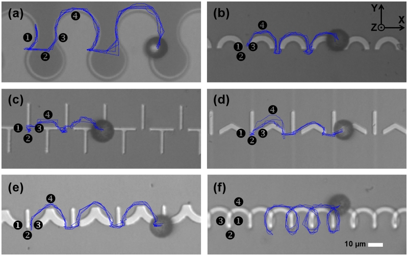
When a vertical field is superimposed on this system, one of the energy wells is eliminated. Due to the penalty of switching between north and south poles, these conditions result in closed loop particle trajectories for all magnetic tracks having only positive curvatures. We hypothesize that magnetic tracks consisting of periodically alternating sections of positive and negative curvatures are required to transport magnetized particles in a conical magnetic field (i.e., a static vertical field superimposed with a rotating horizontal field). The design illustrated in Figure 1, called “drop-shape”, is an example of this design motif, which enables magnetized particles and cells to move in open trajectories, depicted in Figure 2a, where the rotation sense determines the direction of motion. Other geometries having alternating positive and negative curvatures can also be used to transport magnetized objects. The designs illustrated in Figure 2(b-f) are adapted from magnetic bubble technology [23-30].
Figure 1.
The drop-shape pattern for manipulating magnetized particles in a conical magnetic driving field is illustrated. The pattern geometry has gaps, dG, and head diameters, dP, respectively. The external magnetic field, H, traces a cone around the vertical z- direction, where α is the cone angle, i.e. the angle between applied the magnetic field and the substrate normal.
Figure 2.
Bidirectional magnetic conductors for transporting magnetic particles in a conical magnetic field. The horizontal and vertical magnetic field components are fixed at 45Oe, while the in-plane field component rotates at a driving frequency of 0.1Hz. The numbers 1, 2, 3, and 4 depict the sequence of stable positions of the magnetized particles in a clockwise rotating field, consistent with the notation of magnetic bubble literature. The 1 position corresponds to an in-plane field along the +x direction, with the rest of the numbers corresponding to sequential 90° clockwise rotations. The blue lines depict the trajectories of magnetic particles extracted from video data. The patterns shown are hereafter denoted (a) drop-shape pattern, (b) C pattern, (c) TI pattern, (d) VI pattern, (e) YI pattern, and (f) spiral pattern. Two example trajectories are shown in Supplementary Movies S1 and S2.
The numbers in Figure 2 depict the sequence of stable positions for particles in a field that is rotated with 90° intervals in the clockwise direction. To better visualize the spread of experimental trajectories, we overlay the trajectories of several different particles on each magnetic track. Less spread in the trajectories is indicative of more reliable device operation. Supplementary Movies S1 and S2 show examples of particle trajectories along these magnetic tracks.
The transport mechanism in a conical magnetic field involves smooth transport along the sections of positive curvature, and then sudden transitions at sections of negative curvature. In order to systematically study the transport properties, we define a dimensionless parameter, β = dP/dG, where dP and dG refer to the particle and gap size, respectively (See Fig. 1). For the track geometries of Figure 2(b-f), we observed open trajectories only for dimensionless ratios, β ≥ 5, shown in Figure 2(b-e). This large ratio poses a challenge due to the constraints in typical lithographic processes, which prevents the fabrication of gaps smaller than ~2-μm in our mask aligner. The drop-shape pattern, illustrated in Fig. 1 and Fig. 2a, on the other hand, can transport particles with a wider size range (β > 0.14), which makes it ideal for small particle and cell manipulation. Finally, we note that all of the geometries presented in Figure 2 have mirror symmetry, and thus the trajectories are reversible when the field rotates in the opposite direction, thus behaving as efficient bidirectional conductors.
To compare the conductivity of the different magnetic track patterns, we measured the maximum speed of 15.6-μm beads on each pattern by characterizing the peak in the velocity vs. frequency relationship. The results are summarized in Table 1, which clearly show that the drop-shape geometry can transport magnetic objects at the highest speeds, with a peak velocity of ~22.5 μm/s. The drop-shape pattern has the additional advantage of allowing beads as small as 2-μm to be transported along the magnetic tracks, whereas the other patterns were only capable of transporting beads with diameters larger than 10-μm.
Table 1.
The maximum magnetophoretic velocities obtained for 15-μm diameter magnetic beads on the conductor geometries introduced in Figure 2.
| Type | Maximum Speed (μm/s) |
|---|---|
| Drop-shape, pattern | 22.5 |
| C pattern | 7.8 |
| TI pattern | 9.6 |
| VI pattern | 60 |
| YI pattern | 3.5 |
| Spiral pattern | 3.0 |
Unidirectional conductors
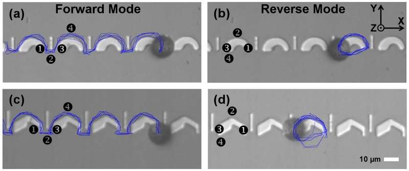
We also characterize the transport properties of track geometries without mirror symmetry, shown in Figure 3. When the field rotates in the clockwise direction (panels on the left column), the magnetic particles move in open trajectories (forward mode); however, when the field rotation sense is reversed (right column) the magnetic particles moves in closed orbits (reverse mode). The origin of this conduction asymmetry results from the deeper energy well that appears near the thicker segment of the track. The divergence in these trajectories can be analyzed by starting from a common position (1), which corresponds to the energy minima for a conical magnetic field with the in-plane component aligned in the positive x- direction. For this field direction, the starting position is on the right side of the thinner edge of the curved magnet. When the conical field rotates by 90° in the clockwise direction, in which the field now points in the negative y- direction, the particle can escape the thinner edge of the curved magnet and move to the immediately adjacent I-bar, denoted as position (2). From there, the particle moves to the left (thicker) edge of the curved magnet when the field rotates by another 90° (field now points in the negative x-direction), denoted as position (3). Next, the particle moves around the positive curvature of the curved magnet and arrives at position (4) (field now points in the positive y-direction), and finally returns to position (1) on the adjacent unit cell when the rotation cycle is completed.
Figure 3.
Asymmetric magnetic tracks are used for uni-directional transport of magnetic particles in a conical field. In a clockwise rotating field, the magnetic particles have open orbits (a,c), corresponding to the forward bias mode. In a counterclockwise rotating field, the magnetic particles move in closed orbits (b,d), corresponding to the reverse bias mode. In all panels, the in-plane and vertical field components are fixed at 45 Oe, while the driving frequency is 0.1 Hz. The numbers 1, 2, 3, and 4 depict the sequence of stable positions of the magnetized particles in a clockwise rotating field (a,c) and a counterclockwise rotating field (b,d). The 1 position corresponds to an in-plane field along the +x direction, with the rest of the numbers corresponding to sequential 90° rotations. The blue lines depict the trajectories of magnetic particles extracted from video data. Some of these trajectories are shown in Supplementary Movie S3.
On the other hand, if the field rotates in the counterclockwise direction, then the particle moves in a closed orbit trajectory. Starting from the right (thinner) edge of the curved magnet, again denoted as position (1), the particle moves around the positive curvature on top of the curved magnet as the field rotates counterclockwise by 90° to position (2). As the field rotates another 90°, the particle moves to the left (thicker) edge of the curved magnet, denoted as position (3). However, due to the deeper energy minima of position (3), the particle never crosses over to the I-bar in position (4), which maintains the particle in a closed orbit that is circulating continuously around the curved magnet. Supplementary Movie S3 provides an example of this behavior. These asymmetric magnetic tracks are thus efficient unidirectional conductors, acting as the corollary of an electrical diodes.
Drop-shape pattern
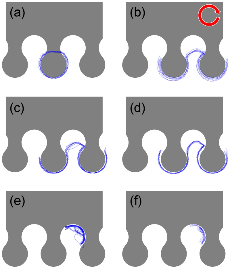
Since the drop-shape pattern is capable of transporting smaller particles, its transport properties are studied in greater detail. Figure 4 illustrates the low-frequency (adiabatic) motion of magnetic particles for magnetic field cone angles ranging from α = 26 – 90°. When the cone angle is less than 30° (e.g., Figure 4(a) for α = 26°), 8.4-μm magnetic particles move in closed loop trajectories around the head of the drop-shape (See Supplementary Movie S4). When the cone angle is α = 30 – 60°, the magnetic particles move in open trajectories (Figure 4(b-d) and Supplementary Movie S2). When the cone angle is greater than 60° (Figure 4(e) α = 63°, and Figure 4(f) α = 90°), the magnetic particles move in closed loop trajectories at the base of the drop (See Supplementary Movie S5). The optimum conditions for repeatable magnetic particle conduction occurs at a cone angle of α = 45 - 50°, where the trajectories are tightly bunched together. (See blue lines in Figure 4d).
Figure 4.
The trajectories (blue lines) of 8.4-μm diameter magnetic particles are shown for magnetic field cone angles of (a) α = 26°, (b) α = 37°, (c) α = 45°, (d) α = 53°, (e) α = 63°, and (f) α = 90°. The red arrow depicts the field rotation sense. These trajectories can be observed in Supplementary Movies S2, S4 and S5.
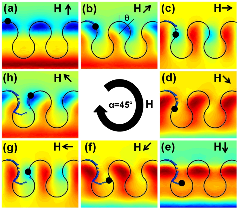
To understand the dynamics of the particle trajectories, finite element methods were used to model the dipolar potential energy landscapes. Figure 5 illustrates the sequence of potential energy landscapes that occurs as a function of time for a α = 45° field cone angle. The energy landscape is plotted at a height of 4.2-μm, which corresponds to the vertical position of the center of the 8.4-μm particle. Starting from Figure 5a in which the horizontal component of the field is aligned in the positive y- direction, the energy minima (blue area) move around the sections of positive curvature at the head of the drop-shape (See Figs. 5(a-d)). When the in-plane field component reaches the critical angle of θ≈135° (See Figure 5d), the track geometry switches from positive to negative curvature, which repels the magnetic particle away from the base of the drop-shape. In Figure 5(e-f), the energy minima move horizontally, arriving at the curvature inflection point of the adjacent unit cell. From there, the energy minima move around the positive curvature of the drop-shape, arriving at the same starting position but advanced by one unit cell period. The experimental trajectories of magnetic particles are overlaid on the energy landscape in Figure 5 and show the strong agreement with simulation. Supplementary Movie S6 illustrates the motion of the potential energy landscape in a rotating external field with a cone angle of α = 45°.
Figure 5.
Dipolar energy landscapes are presented as a function of the in-plane field component. The energy landscapes are produced by finite element simulations for field cone angle of α = 45° and in-plane field angles of (a) θ = 0°, (b) θ = 45°, (c) θ = 90°, (d) θ = 135°, (e) θ = 180°, (f) θ = 225°, (g) θ = 270°, and (h) θ = 315°. The black arrows depict the external field direction. The blue and red regions represent energy minima and maxima, respectively. The blue dots depict the experimental particle trajectories for 8.4-μm magnetic particles. The energy landscape dynamics is shown in Supplementary Movie S6.
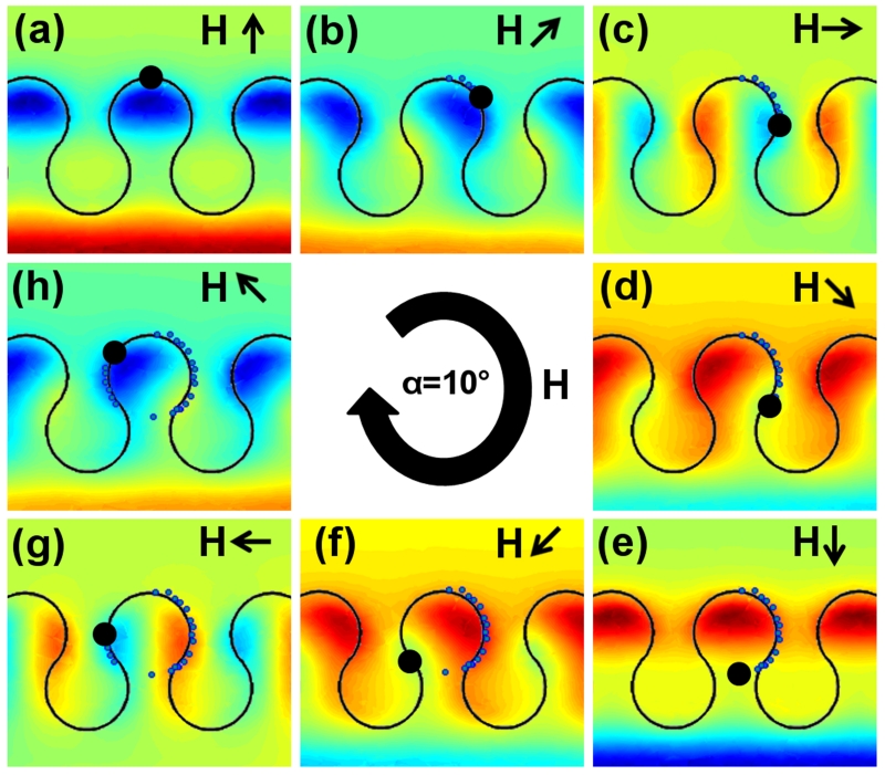
Figures 6(a-h) illustrates the sequence of potential energy landscapes for a 10° field cone angle. Similar to the case of the α = 45° cone angle, the energy minima (blue regions) circulate around the positive curvature at the head of the drop-shape (See Figs. 6(a-d)). At a critical angle of θ≈135°, the strong vertical field results in an energy minima appearing on top of the magnetic pattern directly below the head of the drop-shape (See Figs. 6(d-f)). From there, the energy minima move across the top of the magnetic pattern, ending up at the opposite side of the same unit cell. These field conditions thus result in closed loop circular trajectories around the head of the drop-shape.
Figure 6.
Dipolar energy landscapes are presented as a function of the in-plane field component. The energy landscapes are produced by finite element simulations field cone angle of α = 10° and in-plane field angles of (a) θ = 0°, (b) θ = 45°, (c) θ = 90°, (d) θ =135°, (e) θ = 180°, (f) θ = 225°, (g) θ = 270°, and (h) θ = 315°. The black arrows depict the external field direction. The blue and red regions represent energy minima and maxima, respectively. The blue dotted lines depict the experimental particle trajectories for 8.4-μm magnetic particles.
The simulation results for an in-plane rotating magnetic field, i.e., α = 90°, shows a similar trend with experiments; however, the motion of the energy minima and its corresponding energy barriers are more difficult to discern, and thus are not shown here. The transport mechanism involves the erection of energy barriers at different points in the cycle, which prevent the particles from being transported in open trajectories.
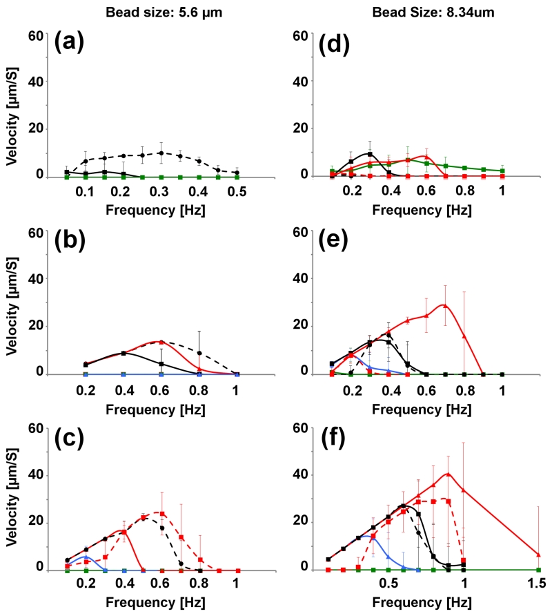
We also conducted higher frequency (non-adiabatic) studies of the particle velocities as a function of the driving frequency. Figure 7 depicts the results for different field angles and field strengths ranging from 25-100 Oe, and cone angles of α = 26 - 90°. The effect of particle diameter was also studied, where the left column shows the trajectories of 5.6-μm particles (Figure 7(a-c)), while the right column shows the trajectories of 8.4-μm particles (Figures 7(d-f)). As expected, these results reveal that increasing the magnetic field strength enables higher top speeds in higher operating frequencies, and that the 8.4-μm particles can achieve higher top speeds (~0.9Hz) than the 5.6-μm particles (~0.6Hz). Particles could be transported only within a specific range of cone angles (i.e., 30° < α < 60°), thus particles were trapped in closed orbits for all driving frequencies when the cone angle is α = 90° (see Figure 7 denoted by the green line and data points).
Figure 7.
The velocities of magnetic particles as a function of frequency are shown for the drop-shape pattern. The left-column shows data for 5.6-μm diameters, while the right column shows data for the 8.4-μm particles. The first, second, and third rows show the data for 25 Oe, 50 Oe, and 100Oe field strengths, respectively. The field cone are depicted as follows: angles of α = 26° (dashed red), α = 37° (dashed black), α = 45° (solid red), α = 53° (solid black), α = 63° (blue), and α = 90° (green).
Cell manipulation
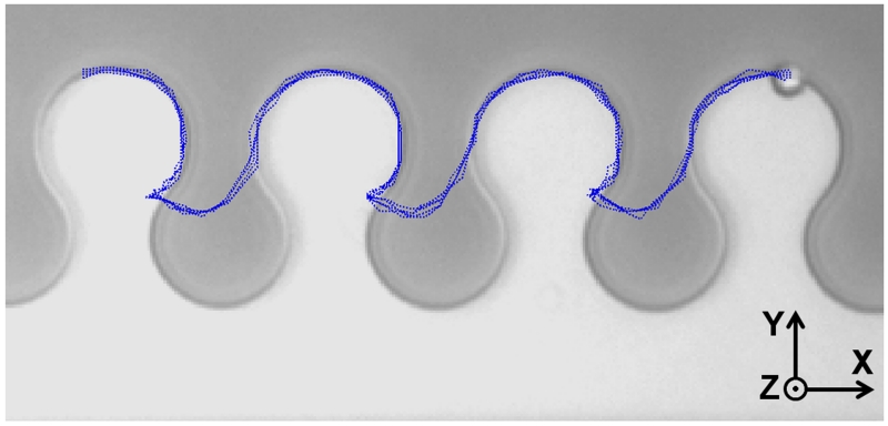
To demonstrate the utility of these magnetic conductor geometries, we study the behavior of magnetically labeled human T cells on the drop-shape pattern in a conical magnetic field (Figure 8, Supplementary Movie S7). The blue dotted lines representing multiple cell trajectories indicate this geometry can reliably transport single cells in α = 45° field cone angles. The use of a 3-D driving field allows the positions of the cell in the conductor track to be uniquely defined at each point in the cycle, and avoids the degeneracy of the previously studied in-plane magnetizing fields.
Figure 8.
Magnetically labeled human T cells are transported in a clockwise rotating conical field. The in-plane and vertical field components are fixed at 45 Oe, corresponding to a cone angle of α = 45°. The driving frequency is 0.1Hz. The trajectories of individual cells are shown with the blue dotted lines.
Particle separation
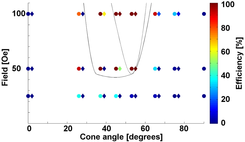
Our results suggest that it is possible to implement size-based separation of particles by modulating the cone angle and field strength of the rotating external field. The phase diagram in Figure 9 shows the percentage of magnetic particles moving in open trajectories as a function of the external field strength and cone angle. The data for 5.6-μm diameter particles are depicted as diamonds, while the 8.4-μm diameter particles are depicted as circles. The hand-drawn solid and dotted lines for these two types of particle are used as guides to the eye, which define the boundaries of their respective transport regimes.
Figure 9.
The field vs. cone angle phase diagram on the drop-shape pattern is shown for 5.6-μm diameter particles (diamonds) and 8.4-μm diameter particles (circles). The boundaries of the conducting and non-conducting regimes for particles are represented with a dotted line and a solid line for the 5.6-μm and 8.4-μm diameter particles, respectively. A window appears around α = 30-50° where the 8.4-μm diameter particles can be transported across the substrate, whereas the 5.6-μm particles cannot.
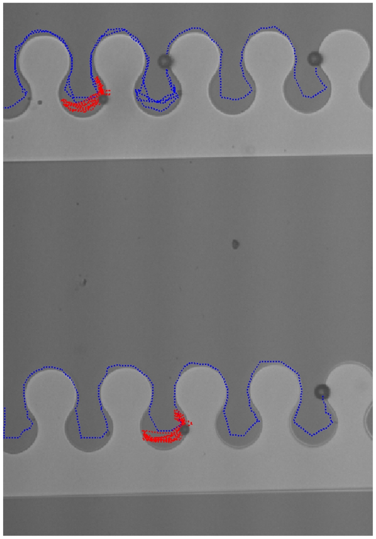
The phase diagram suggests that a cone angle of α = 45° and field strength of ~50 Oe are a good choice for separating the two magnetic particle types. To test this prediction, a mixture of the two magnetic particle types was dispersed on the chip in the above-specified operating conditions. Figure 10 and Supplementary Movie S8 show that the larger particles move in open trajectories, whereas the smaller particles are trapped in closed orbits. Blue and red dotted lines in Figure 10 represent trajectory of large and small particles, respectively. As observed in Supplementary Movie S8, the periodic encounters between different beads can introduce imperfections in the separation process, in which one bead can drag another during brief intervals of motion. However, the dipolar interactions between these beads tend to be repulsive at cone angles of α = 37°, which is below the magic angle of α = 54°. This dipolar repulsion inhibits irreversible aggregation and allows the separation process to be maintained.
Figure 10.
Size based separation of particles. The in-plane and vertical field components are fixed at 30 Oe and 40 Oe, respectively, corresponding to a cone angle of α = 37°. The driving frequency is 0.1Hz. The trajectories of the 8.4-μm diameter beads are shown with the blue dotted lines, while the trajectories of the 5.6-μm diameter beads are depicted with the red dotted lines. The trajectories are taken from Movie S8.
Conclusions
In electrical circuits, the repulsion between individual electrons leads directly to the current/voltage relationships of capacitors, transistors, and other lumped circuit elements. This repulsion prevents charge packets from building up inside conductors, and self-limits the charge and current storage capabilities of capacitors and inductors. Prior to this work, however, it was unclear how to achieve similar self-repulsion in magnetophoretic circuits for transporting physical objects, and thereby improve the analogy with electrical circuits. We overcome this potential limitation by re-designing new magnetic conductor geometries capable of transporting magnetic particles and magnetically labeled single cells in a 3-dimensional conical magnetic driving field. When the track geometries possess mirror symmetry, they behave as bidirectional conductors, while those without mirror symmetry behave as unidirectional conductors. The vertical field also eliminates the degeneracy in the clock cycle, and allows for the position of the magnetized object to be uniquely defined, which improves the synchronization with the external driving field over previously studied systems driven by an in-plane rotating field. Though we did not explicitly analyze the maximum particle density that can be reliably transported on these circuits, we expect that the system can handle at most 1-2 magnetic objects per unit cell. In analogy with electronic conductors, this would correspond to the charge carrier density of a highly conductive metal, such as Au, Ag, or Cu, which has 1-2 free charge carriers per atom.
Among all the magnetic track geometries studied here, the drop-shape pattern was most adept at transporting small particles and single cells. In low frequencies, the magnetic particles move in open trajectories when the magnetic field cone angle is in the range α = 30°– 60°, with an optimal cone angle of α = 45° - 50°. The transport dynamics of particle conduction were also studied as a function of frequency, which allowed for an experimental phase diagram of the particle motion to be studied for different experimental conditions.
The strong agreement between experiment and simulation shows the potential for adapting ideas from the magnetic bubble literature to build other circuit elements, such as transistors and capacitors, and integrate them into complex integrated circuits, such as random access memories. Based on the demonstrated ability to transport single cells and separate objects based on size, these results pave the way for building highly controllable manipulation platforms for lab on a chip systems.
Supplementary Material
ACKNOWLEDGMENTS
The authors are thankful to Hamidreza Toroghi for providing the 3D illustration in Figure 1a, and to Shaohua Lin for helpful discussion on FEM analysis. This research was supported by the Creative and Novel Ideas in HIV Research Program (CNIHR) through a supplement to the University of Alabama at Birmingham (UAB) Center For AIDS Research funding (P30 AI027767). This funding was made possible by collaborative efforts of the Office of AIDS Research, the National Institutes of Allergies and Infectious Diseases, and the International AIDS Society. This study was supported by NIH grant 1R56AI112360, NIH training grant T32GM008555, and by the Duke University CFAR (5P30 AI064518).
REFERENCES
- [1].Zhu H, Lin X, Su Y, Dong H, Wu J. Biosens. Bioelectron. 2015;63:371–378. doi: 10.1016/j.bios.2014.07.072. [DOI] [PubMed] [Google Scholar]
- [2].Ge S, Liu W, Schlappi T, Ismagilov RF. J. Am. Chem. Soc. 2014;136:14662–14665. doi: 10.1021/ja507849b. [DOI] [PubMed] [Google Scholar]
- [3].Kokalj T, Pérez-Ruiz E, Lammertyn J. N. Biotechnol. 2015;32(5):485–503. doi: 10.1016/j.nbt.2015.03.007. [DOI] [PubMed] [Google Scholar]
- [4].Karabacak NM, et al. Nat. Protoc. 2014;9(3):694–710. doi: 10.1038/nprot.2014.044. [DOI] [PMC free article] [PubMed] [Google Scholar]
- [5].Devaraju NSGK, Unger MA. Lab Chip. 2012;12:4809–4815. doi: 10.1039/c2lc21155f. [DOI] [PubMed] [Google Scholar]
- [6].Abonnenc M, et al. J. Immunol. 2013;191:3545–3552. doi: 10.4049/jimmunol.1300890. [DOI] [PubMed] [Google Scholar]
- [7].Tierno P, Sagues F, Johansen TH, Fischer TM. Phys Chem Chem Phys. 2009;11:9615–9625. doi: 10.1039/b910427e. [DOI] [PubMed] [Google Scholar]
- [8].Tierno P, Reddy SV, Yuan J, Johansen TH, Fischer TM. J. Phys. Chem. B. 2007;111:13479–13482. doi: 10.1021/jp0755589. [DOI] [PubMed] [Google Scholar]
- [9].Tierno P, Johansen TM, Fischer TM. Phys. Rev. Lett. 2007;99:038303. doi: 10.1103/PhysRevLett.99.038303. [DOI] [PubMed] [Google Scholar]
- [10].Tierno P, Fischer TM. Phys. Rev. Lett. 2014;112:048302. doi: 10.1103/PhysRevLett.112.048302. [DOI] [PubMed] [Google Scholar]
- [11].Yellen BB, Hovorka O, Friedman G. PNAS. 2005;102:8860–8864. doi: 10.1073/pnas.0500409102. [DOI] [PMC free article] [PubMed] [Google Scholar]
- [12].Yellen BB, Erb RM, Son HS, Hewlin R, Jr, Shang H, Lee GU. Lab Chip. 2007;7:1681–1688. doi: 10.1039/b713547e. [DOI] [PubMed] [Google Scholar]
- [13].Kose AR, Fischer B, Mao L, Koser H. PNAS. 2009;106:21478–21483. doi: 10.1073/pnas.0912138106. [DOI] [PMC free article] [PubMed] [Google Scholar]
- [14].Kortman H, et al. Lab Chip. 2009;9:576–585. doi: 10.1039/b809150a. [DOI] [PubMed] [Google Scholar]
- [15].Guo X, Zhu R. Biosens. Bioelectron. 2015;68:529–535. doi: 10.1016/j.bios.2015.01.052. [DOI] [PubMed] [Google Scholar]
- [16].Lee H, et al. Lab Chip. 2007;7:331–337. doi: 10.1039/b700373k. [DOI] [PubMed] [Google Scholar]
- [17].Ohlin M, Iranmanesh I, Christakou AE, Wiklund M. Lab Chip. 2015;15(16):3341–3349. doi: 10.1039/c5lc00490j. [DOI] [PubMed] [Google Scholar]
- [18].Ramser K, Hanstorp D. J. Biophotonics. 2010;3:187–206. doi: 10.1002/jbio.200910050. [DOI] [PubMed] [Google Scholar]
- [19].Skelley AM, et al. Nat. Methods. 2009;6:147–152. doi: 10.1038/nmeth.1290. [DOI] [PMC free article] [PubMed] [Google Scholar]
- [20].Lim B, Reddy V, Hu X, Kim K, Jadhav M, Abedini-Nassab R, Noh Y, Lim YT, Yellen BB, Kim C. Nat. Commun. 2014;5:3846. doi: 10.1038/ncomms4846. [DOI] [PubMed] [Google Scholar]
- [21].Abedini-Nassab R, Murdoch DM, Kim C, Yellen BB. J. Appl. Phys. 2014;115(24) [Google Scholar]
- [22].Abedini-Nassab R, Joh DY, Van Heest M, Yi I, Baker C, Taherifard Z, Margolis DM, Garcia-Martinez V, Chilkoti A, Murdoch DM, Yellen BB. Adv. Mater. 2015 doi: 10.1002/adma.201502352. DOI: 10.1002/adma.201502352. [DOI] [PMC free article] [PubMed] [Google Scholar]
- [23].Eschenfelder AH. Springer Series in Solid-State Sciences. (Second edition) 1981;14 [Google Scholar]
- [24].Sperious V, Rosenthal YD, Humphrey FB, Kobayashi T. IEEE T. Magn. 1979;15(1):875–879. [Google Scholar]
- [25].Bonyhard PI, Smith JL. IEEE T. Magn. 1976;12(6):614–617. [Google Scholar]
- [26].Bobeck A, Bonyhard PI, Geusic JE. P. IEEE. 1975;63(8):1176–1195. [Google Scholar]
- [27].Cohen MS, Beall G, Hsieh W, Chang H. IEEE T. Magn. 1977;13(5):1264–1266. [Google Scholar]
- [28].Cohen MS, Chang H. P. IEEE. 1975;63(8):1196–1206. [Google Scholar]
- [29].Chang H, Fox J, Lu D, Rosier L. IEEE T. Magn. 1972;8(2):214–222. [Google Scholar]
- [30].Perneski A. IEEE T. Magn. 1969;5(3):554–557. [Google Scholar]
- [31].Georgios K, James CS, Prakash M. Nat. Phys. 2015;11:588–596. [Google Scholar]
- [32].Hucknall A, Kim DH, Rangarajan S, Hill RT, Reichert WM, Chilkoti A. Adv. Mater. 2009;21:1968. doi: 10.1002/adma.200803125. [DOI] [PMC free article] [PubMed] [Google Scholar]
Associated Data
This section collects any data citations, data availability statements, or supplementary materials included in this article.


