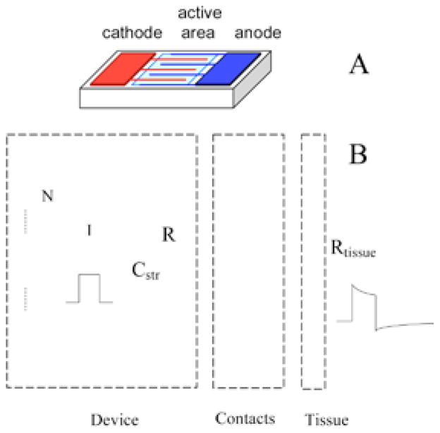
FIGURE 2.
Electrical model of the FLAME stimulators, 60 which includes multiple photodiodes in series to increase the output voltage compliance, the interface with the tissue at the contacts, and the tissue impedance (B). The drawing on top shows the arrangement of the photodiode active area and the contacts on the wafer (A). Some decrease of output current occurs during the pulse due to the current that flows through the intrinsic diodes as the device voltage is increasing with charging of contact capacitors. Contact capacitors are discharged passively through the parallel resistor (R) during the off phase of the pulse cycle. A small stray capacitor (Cstr) is placed between the device terminals during fabrication.

