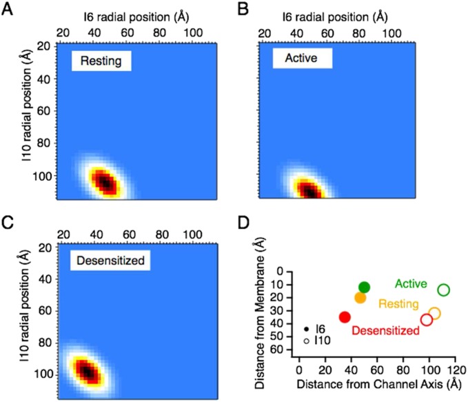
Fig. S7.
Triangulation of the I6 and I10 fluorophores. Heat maps of the most probable radial positions of the inserts based on FRET distances, the axial distances from quenching by DPA and the expected length of random coils for the resting (A), active (B), and desensitized (C) states. (D) Radial and axial positions (from Fig. S6) of the I6 and I10 inserts.

