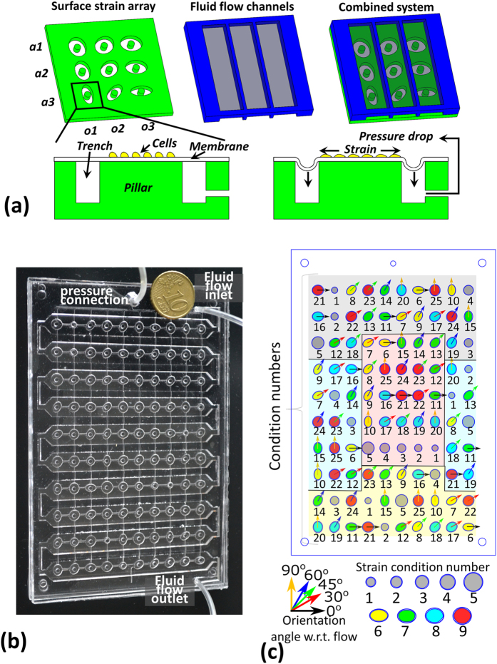
Figure 1.
A schematic representation of the reported device (a) illustrates how strains are generated by stretching a membrane over a pillar and how these strains are combined with shear stresses using an overlaid flow channel. The schematic also shows how varying degrees of anisotropic strains (a1, a2, a3) are generated by using various aspect ratios of the strain actuating trenches, and that by using various orientations (o1, o2, o3) of the trench with respect to the flow channel, various orientations of the anisotropic strains with respect to the shear stresses can be tested. The developed prototype (b) and the layout of the various trench shapes (c) demonstrate how the various conditions are distributed randomly on the device to avoid location specific effects, while keeping a replicate of each condition in four regions that can be expected to differ. These four regions that the device is divided into are depicted in different colors – gray (near inlet), yellow (near outlet), blue (near bends) and red (mid-channel).

