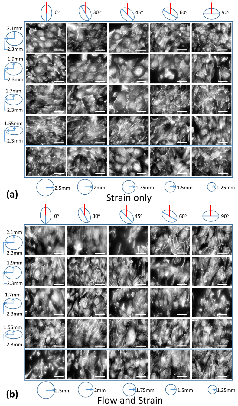
Figure 5. Fluorescent images of HUVECs stained with Alexa 488 phalloidin were taken using a long working distance 20× objective with BD Pathway for multiple (an)isotropic strain regimes at multiple angles to the fluid flow direction.
The cells are shown after a 24 hour strain only (a) or a 24 hour flow and strain (b) stimulation under media containing 5% dextran (high viscosity). Scale bar −100 μm. In each image set, the conditions are arranged by the degree of anisotropy in the rows and by the orientation of the trench major axis in the columns. Ellipses of various aspect ratios drawn on the left depict the various degrees of anisotropy in the respective rows and the circles of various sizes drawn at the bottom depict the various equibiaxial strains in the last row. The ellipses drawn on the top of each image set represent the trench orientations while the red lines represent the flow direction or just the orientation of the flow channel (in the case of strain only stimulation).

