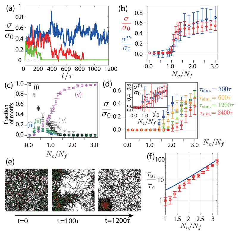
Fig. 3.
Stress in a network of motors and filaments, with and without cross-linker turnover. (a) Time evolution of the normalized stress σ/σ0 for τc−1 = 0, Nc = 1.2Nf (blue), τc = 100τ, Nc = 1.6 Nf (red) and τc = 100τ, Nc = 1.2Nf (green) (σ0 = f0lmNm/W2). (b) Steady-state isotropic stress σ (circles) and motor stress σm (diamonds) as a function of the cross-linkers number Nc for τc−1 = 0. (c) Fraction of different configurations in Figs. 2(i)-2(v) at steady state as a function of the cross-linker number Nc for τc−1 = 0. (d) Isotropic stress σ as a function of the cross-linker number Nc, for a finite cross-linker lifetime τc = 100τ, and for several simulation times (τsim. = 300, 600, 1200 and 2400τ). Stress within the motors σm is shown in the inset for τsim. = 300 and 2400τ. (e) Snapshots of a simulated network with cross-linker turnover (Nc = 1.2Nf, τc = 100τ). (f) Stress decay time τst as a function of the cross-linker number Nc with cross-linker turnover (τc = 100τ). Solid line, theoretical prediction (see the main text). Other parameters are Nf = 1000, Nm = 100, τf−1 = 0, , lf = 2lm, W = 10lm,τm = 100τ, and .

