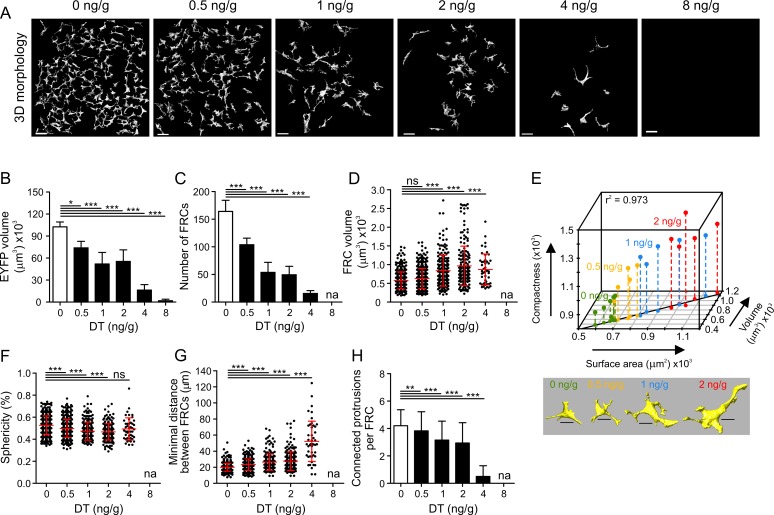
Fig 4. Alterations in FRC morphology following partial FRC ablation.
(A) Representative 3-D single-cell reconstructions of the T cell zone FRC network in Ccl19eyfp/idtr mice injected twice IP with indicated doses of DT. (B) Total volume of the EYFP+ T cell zone FRC network for indicated doses of DT. (C) Number of single FRCs per acquired T cell zone for indicated doses of DT. (D–H) Single-cell analysis of FRC volume (D); correlation of surface area, volume, and compactness (E); sphericity (F); minimal distance between FRCs (G); and connected protrusions per FRC (H). Values in (B–C) represent mean ± SD for each T cell zone FRC dataset and in (D, F–H) represent mean ± SD for each single FRC for 3–6 mice per group from two independent experiments. Vertical lines in the 3-D plot (E) represent projections on the bottom 2-D plane. The line on the 2-D plane represents a linear regression model for surface area and volume with indicated Pearson correlation coefficient r2 = 0.973, p = 2.71 x 10⁻¹⁶ (Fisher’s F test). Images below are representative 3-D reconstructions of FRCs for indicated doses of DT. Scale bars represent 30 μm (A) and 10 μm (E). * p < 0.05, ** p < 0.01, *** p < 0.001 (one-way ANOVA with Tukey’s post-test [B–D and F–G] or Kruskal-Wallis test with Dunn’s post-test [H]). ns, not significant; na, not applicable.

