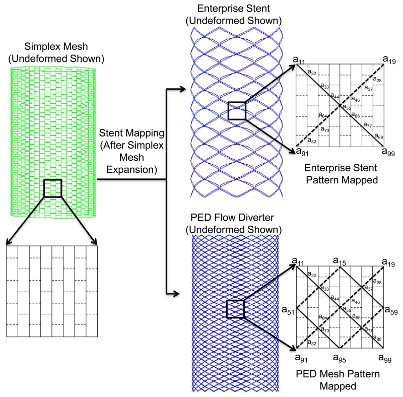
Figure 5.
Stent mapping pattern on the deployed simplex mesh, illustrated on an idealized cylinder. To illustrate the Enterprise stent model (top), Wire 1 (solid line in insert) is obtained from joining vertex coordinates a11, a22,…, a99, and Wire 2 (dashed line in insert) is obtained from joining vertex coordinates a19, a28,…, a91. Wire 1 and Wire 2 are repreated 8 times to obtain a total of 16 wires. For the PED pattern (bottom), Wire 1 and Wire 2 are obtained in the same manner and repeated 24 times to produce a total of 48 wires.

