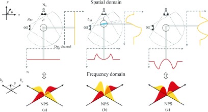
FIG. 2.
Demonstration of how the bowtie filter and object position can jointly impact the number of x-ray photons (N) received by each detector channel. (a) A centered object with perfectly matched bowtie filter; (b) an off-centered object with the same bowtie filter; (c) a centered object with a bowtie filter that is designed for a much larger object. N0 represents the expected photon number prior to the bowtie filter and the image object; μbt and μ are the linear attenuation coefficients of the bowtie filter and the image object, while Lbt and L (highlighted in blue) denote their thicknesses, respectively. The “+” symbol marks the isocenter of the scan FOV. The shaded areas highlight detector elements contributing to the local NPS of each ROI when fan-to-parallel beam rebinning is used before reconstruction. (See color online version.)

