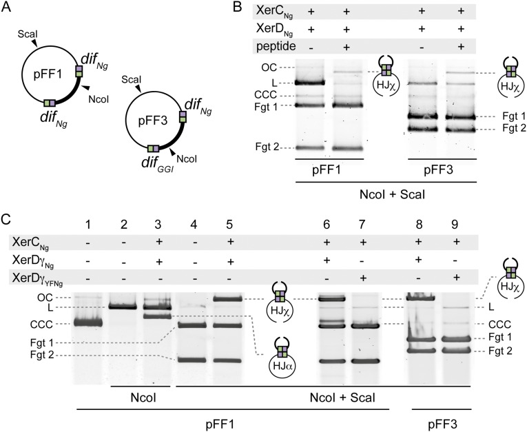
Fig. S2.
In vitro and in vivo recombination. (A) Schematic map of pFF1 and pFF3 plasmids, which are used as substrates in the in vitro recombination experiments. Restriction cleavage sites used for product simplification are represented. (B) HJ intermediate captures. The recombination reactions (Methods) were supplemented with the peptide WRWYCR (10 μM). CCC, OC, and L forms of the substrate plasmids are represented. Fgt1 and Fgt2 correspond to the DNA fragments obtained after Nco1 and ScaI digestion. (C) HJ intermediates characterization. Lanes 1–5: The recombination reactions (Methods) were either digested with NcoI (forms HJα; lane 3) or with NcoI and ScaI (forms HJχ; lane 5). Lanes 6–9: Purified XerDγYFNg (Methods) (catalytically defective variant of XerDγNg) was used in the HJ intermediate formation assay (Methods).

